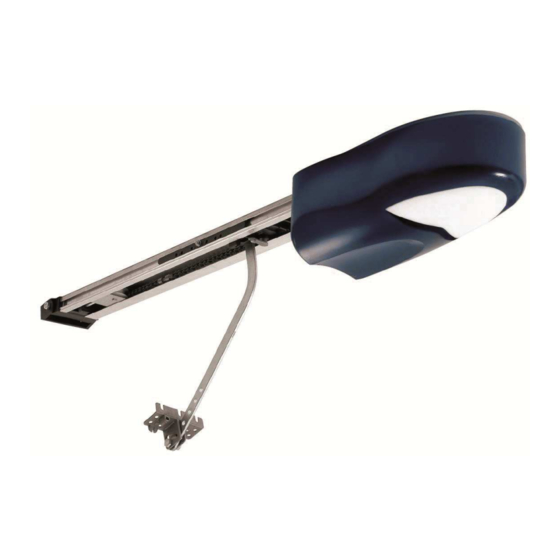
Allmatic CT ACTION 09 Instrucciones de instalación - Página 3
Navegue en línea o descargue pdf Instrucciones de instalación para Unidad de control Allmatic CT ACTION 09. Allmatic CT ACTION 09 8 páginas. For sectional doors

4. Settings
This chapter contains important information for a safe and correct installation. Follow scrupulously all the instructions, because a wrong installation
can cause breaks or malfunctioning of the automation.
Warning: before starting the automation's programming deactivate all the gate's locks (unlocked door handle,
open lock).
4.1 Preliminary checks
Before giving power supply to the system, check all the wirings carried out. Particularly, check that no damages, short –circuits among cables and
that all the accessories are connected to the terminal board in the points indicated on the scheme of previous page. Once given power supply check
that:
1.
Check that there are no excessive frictions; to that aim, unlock the slide and with the necessary precautions move manually the gate in
opening and in closing bringing it on the anchorage point of the bar to the shutter self.
The force necessary to carry out this action must not exceed Kg. 15 (150N).
2.
Check that the led POWER is turned on fix and that the shutter is in closing position.
3.
Check that the radio module is inserted.
4.
Check that the connection of the motors and of the encoders following the procedure described below; This procedure allows to verify the
rotation sense of the motors, eventual jamming or malfunctioning during the movement of the wing. It is important to carry out this control to
point out wiring mistakes or anything else can jeopardize a normal functioning.
NOTE : during these operations the photocells, the radio and the buttons are NOT active.
SW1 position
MAN
AUT
SW1 position
Yes
MAN
AUT
4.2 Manual moving
This procedure must be carried out ONLY by the installer and ONLY during the setting up of the system. This movement must be carried out only in
particular conditions where it is not possible to bring again the shutter in closing position in automatic modality.
SW1 position
MAN
AUT
WARNING: the reactivation of the automatically modality (AUT) involves the use of the reached position as
position of totally closing.
WARNING: during the manual operation the anti – squashing function is excluded.
4.3 Memorization of the transmitters (only with closed door)
Memorize at least one 1 channel transmitter. The control unit is supplied with decoding. The control unit is supplied with rolling code decoding, to
change the decoding type (see paragraph 5.9). During the normal functioning the first button carries out the step – by step function (opening and
closing), the second button (optional) handles the function of turning on courtesy light.
SW1 position
AUT
MAN
Press the first button of the transmitter. The flash-
ing light emits 2 beep.
The 1° button is memorized. Press and release the
RED key. The led turns on fix.
Press the 2° button of the transmitter. The flashin g
light emits 1 slow blinking followed by a quicker one.
The two transmitters are memorized and the procedure finishes.
6-1622356 rev.4 09-07-2013
Press the BLUE button
with an impulse. The gate
must open.
SI
Release the BLUE button and press the
YELLOW one. The gate must close
itself. Bring it again in closing position.
To close the door
To open the door
Press and release the RED button.
The blinking led turns on fix.
Yes
Yes
Yes
Yes
ITA
The automation does
NO
not move
The automation clos-
NO
es itself
NO
Check the wirings
and repeat the proof.
Press the YELLOW button
Press the BLUE button
NO
Check that the door is closed and that SW1 is
in AUTO position and repeat the test.
If the flashing light has emitted 1 slow blinking followed by 1 quick
NO
blinking, the pressed button was already memorized and it is possible
to continue the procedure; in contrary case check that the transmitter
works and that the radio module is inserted. Repeat the test.
NO
Check that the door is closed and that SW1 is
on position AUTO and repeat the test.
Check that the transmitter works, that it has the same decoding set in
NO
the control unit and that the radio module is inserted.
At this point repeat the test.
ENG
FRA
ESP
DEU
POR
Check the wirings
and repeat the proof
Modify the orientation of the 2 jumpers
present on the card. If not present,
invert the motor's phases. Repeat the
proof.
pag. 3 di 8
