Bürkert 6014 Manual de instrucciones - Página 4
Navegue en línea o descargue pdf Manual de instrucciones para Unidad de control Bürkert 6014. Bürkert 6014 19 páginas. 3/2-way solenoid valve
También para Bürkert 6014: Manual de instrucciones (6 páginas)
6.
INSTALLATION
6.1. Safety instructions
DANGER!
Risk of injury from high pressure in the equipment/device.
▶ Before working on equipment or device, switch off the pressure and
deaerate/drain lines.
Risk of electric shock.
▶ Before working on equipment or device, switch off the power supply
and secure to prevent reactivation.
▶ Observe applicable accident prevention and safety regulations for
electrical equipment.
Risk of injury from improper installation.
▶ Installation may be carried out by authorized technicians only and
with the appropriate tools!
▶ Secure system from unintentional activation.
▶ Following installation, ensure a controlled restart.
8
Valve with threaded connection:
→
Use PTFE tape as sealing material.
NOTE!
Caution risk of breakage.
▶ Do not use the coil as a lifting arm.
→
Hold the device with a suitable tool (open-
end wrench) on the body and screw into
the pipeline.
Valve with flanged connection:
→
Remove the cover plate.
→
Loosen the nut on the coil and remove coil.
6.3. Electrical connection with cable plug
DANGER!
Risk of electric shock.
▶ Before working on equipment or device, switch off the power supply
and secure to prevent reactivation.
▶ Observe applicable accident prevention and safety regulations for
electrical equipment.
If the protective conductor contact between the coil and body is
missing, there is danger of electrical shock.
▶ Always connect protective conductor.
▶ Check electrical continuity between coil and body.
Seal
Fig. 3:
Electrical connection with cable plug
10
Type 2508
max. 1 Nm
6.2. Fluid installation
DANGER!
Risk of injury from high pressure in the equipment/device.
▶ Before working on equipment or device, switch off the pressure and
deaerate/drain lines.
Installation position: any, coil preferably upwards.
Procedure:
→
Before installation, clean any possible dirt off the pipelines and flange
connections.
→
If required, install a dirt trap to prevent malfunctions.
Pay attention to the flow direction of the valve.
from 1(P) → 2(A) (Circuit function C) or
from 1(P) → 2(B) (Circuit function D)
Cover plate
Fig. 2:
Valve with flanged connection
WARNING!
Risk of injury due to escaping medium.
▶ Make certain the seals included with delivery are properly seated in
the valve.
▶ Ensure that the manifold is even.
▶ Ensure that the surface quality of the manifold is adequate.
→
Insert the seal into the body.
→
Screw the body onto the manifold (tightening torque: max. 1.5 Nm).
→
Attach the coil and screw on the nut (tightening torque: max. 5 Nm).
Note the voltage and current type as specified on the type label.
→
Check that seal is fitted correctly.
→
Connect and tighten the cable plug (tightening torque: max. 1 Nm).
The cable plug can be turned by 4 x 90°.
Control of pulse version
Correct polarity is essential to ensure that the device functions:
Note identification on the upper side of the coil.
Pulse duration at least 50 ms.
Protective conductor connection
Terminal 2
Terminal 1
Fig. 4:
Pulse version
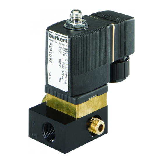
Type 6014
Mesh size:
0,2 – 0,4 mm
Nut
Coil
Seal
Manifold
9