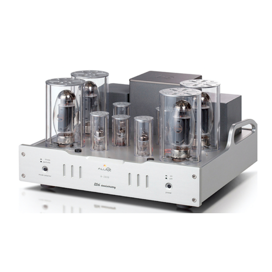
ALLNIC AUDIO A-2000 25th Anniversary SE Manual del usuario - Página 8
Navegue en línea o descargue pdf Manual del usuario para Amplificador ALLNIC AUDIO A-2000 25th Anniversary SE. ALLNIC AUDIO A-2000 25th Anniversary SE 13 páginas. Push-pull stereo power amplifier

to hear it. To avoid the sound, simply switch the A-2000 SE to pentode (beam tetrode) mode prior to turning it
off (see the "On-the-Fly Triode/Pentode Switching section below).
In the case of any failure, please contact Your Allnic dealer for assistance.
"ON-THE-FLY" PENTODE/TRIODE SWITCHING
You can use the Pentode (Beam Tetrode)/Triode "Mode Selector" button at any time during operation to switch
back and forth from Pentode to Triode operation. Press the mode selector button on the left side of the front
panel down to have the A-2000 SE operate in Triode mode; press the button again so it is in the raised position to
have the A-2000 SE operate in Pentode mode.
THE CURRENT METERS
The illuminated meters on the chassis' top plate indicate the current supply to each of the four KT150 gain tubes in
the A-2000 SE. There is one current meter for each channel's pair of KT150 power tubes. There is also a
potentiometer (bias control screw) and a fuse for each KT150.
When you turn on the A-2000 SE, the needle of each current meter should be between the two parallel lines on the
meter face. Any error of current supply to or failure of a KT150 tube is indicated by the needle on the KT150 tube's
respective meter moving out from between these two parallel lines.
TUBES AND TUBE BIAS
th
The A-2000 25
Anniversary SE Stereo Power amplifier uses the following tubes:
• Four (4) x KT150
• Four (4) x 6S4
• Two (2) x 5654
Because of the individual bias for each KT150, it is not necessary to use a matched quad of these power tubes in the
A-2000 SE.
There is a switch on the top plate of the chassis between the front and back KT150s for each for the right and left
channels. Flipping the switch toward the rear of the chassis sets the meter to read the rear KT150 for that channel.
Flipping the switch toward the front of the chassis sets the meter for the front KT150 for that channel. As noted
above, the needle of the meter should always be between the two lines in the centre of the meter. The position of
the needle should be the same for all four KT150s. You may adjust the needle's position between the lines by
turning the potentiometer screw clockwise or counter-clockwise using an appropriately bladed screwdriver. The
position of the needle between the lines will alter the sound.
The needle should always be between the two lines. If the needle of a current meter for a KT150 has moved to the
left of the parallel lines on the meter face, using an appropriately bladed screwdriver, adjust the potentiometer
screw adjacent to that tube by turning the screw clockwise until the needle has returned to between the meter's
parallel lines. If the meter needle has moved to the right of the parallel lines on the meter face, turn the
potentiometer screw counter-clockwise to correct.
If a meter's needle drops to the left limit of the meter's face during operation, this indicates a failure of the related
KT150 tube. You must turn off the A-2000 SE and replace both the fuse (0.5A, 250V, 20mm slow-blow) for that tube
8
