ALLNIC AUDIO HPA-5000 XL Manual del usuario - Página 7
Navegue en línea o descargue pdf Manual del usuario para Amplificador ALLNIC AUDIO HPA-5000 XL. ALLNIC AUDIO HPA-5000 XL 10 páginas. Stereo otl/ocl headphone amplifier
También para ALLNIC AUDIO HPA-5000 XL: Manual del usuario (9 páginas)

Please set the HPA-5000 XL's volume control at "0" when switching between inputs 1 and 2.
INITIAL POWER-ON
Once you have your HPA-5000 XL in place and all connections have been made to your source, you are ready
to turn on the power for your HPA-5000 XL. Before you power up the HPA- 5000 XL, though, be sure you have:
removed ALL the cushion materials from inside the tube chimneys.
•
•
turned the volume control of the HPA-5000 XL down to zero by rotating the single knob on the front of
the HPA-5000 XL counterclockwise until it stops.
checked that all your connections are snug
•
To turn on the HPA-5000 XL, press in the button switch on the left of the front panel. Pressing the power
button again will power down the HPA-5000 XL (See Figure 2). Above the power button is a light. The light
illuminates when the power is on.
OPERATION
Operation is straight-forward. Volume is controlled by the volume knob and inputs are selected with the
input button, as explained above.
When you are finished listening, first turn off your HPA-5000 XL by pressing the power switch on the right
hand side of the unit's front panel; then turn off your sources.
In the case of any failure, please contact your Allnic Audio dealer for assistance.
TUBES
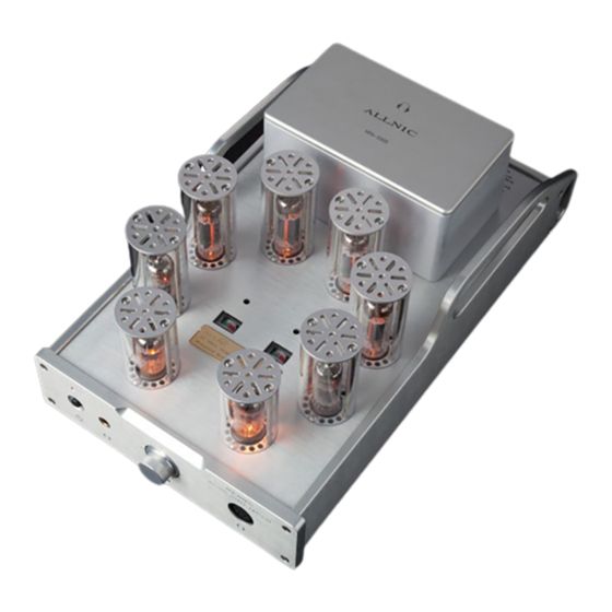
The HPA-5000 XL uses the following tubes (See Figure 3):
• Four (4) x NOS 7233 triode
• Two (2) x NOS E-180CC double triode
• Two (2) x NOS 6AN8 triode-pentode
All consequences of changing or attempting to change tubes are borne by the user unless by express
agreement between the owner and the owner's Allnic dealer. Allnic Audio and its authorized representatives
are not liable in any way whatsoever for any injury or loss incurred by the user or for damage to the HPA-
5000 XL, any of its parts, or tubes or replacement tubes resulting from the user changing or attempting to
change tubes.
TUBE BIAS
Tube bias is monitored by viewing the meter for each of the right and left channels, located on the top of the
chassis (See Figure 3). Bias is correct if the meter's needle is in the center section of the meter, between the
green and red sections. Tube biasing, if required, is performed by using a small screwdriver to rotate the
yellow bias screw directly above the relevant meter so that the meter needle is in the center section of the
meter, between the green and red sections.
8
