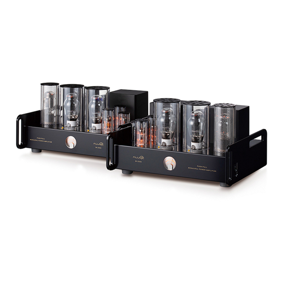
ALLNIC AUDIO M-2500 Manual del usuario - Página 7
Navegue en línea o descargue pdf Manual del usuario para Amplificador ALLNIC AUDIO M-2500. ALLNIC AUDIO M-2500 16 páginas. Px25/300b/kt150 push-pull monoblock power amplifiers

• DO NOT subject the M-2500s to knocks and shocks as you move them around. This advice is meant
particularly for those who may want to place the M-2500s on some kind of after-market isolation
feet or similar devices. Dropping one side of the M-2500s, or the whole of a unit, is not a good
thing to do and may void the warranty.
• DO NOT place the unit near a strong light or heat source.
• DO NOT place anything heavy on the unit.
• DO NOT allow rubber or vinyl materials to rest on the chassis for long periods of time. This could
discolour the metal.
• DO place the M-2500s on a shelf or stand that is stable and not subject to vibration or sudden
shock.
• DO consider using a high-quality power cord, inter-connects and speaker cables. The M-2500s are
highly sensitive electronic devices designed for neutrality and will output what you put into them.
Allnic's ZL (Zero Loss) Technology power and interconnect cables will work synergistically with the
M-2500s.
DO try to place M-2500s away from major sources and potential receivers of RFI and EMI.
•
Though well shielded, the M-2500s will function best away from large power transformers
and other sources of such interference and from other equipment that could be susceptible
to such forms/sources of interference.
• When the M-2500s are moved from a cold to a warm environment, allow sufficient time for any
condensation to evaporate before plugging the M-2500s into an AC connection.
• Do not attempt any repairs.
B.
INPUTS
There are two (2) female inputs (See Figure 6). One accepts a balanced cable with a male XLR connector;
the other accepts a cable with a single-ended, RCA type male connector. On one chassis, these input
connections are located on the right (facing the back) rear of the chassis, with the balanced input closest
to the side edge. The inputs are on the left rear of the chassis on the other M-2500. Between the inputs,
there is a switch to select one of two pin configurations for a balanced cable (i.e., it changes the phase).
The top position is for pin 2" hot" and pin 3 "cold"; the bottom position is for the reverse (in both cases,
pin 1 is ground).
C.
SPEAKER TERMINALS
Each of the M-2500s is equipped with one pair of high-quality speaker terminals (See Figure 6). These
terminals are located in the middle of the rear panel of each M-2500 chassis, with the red marked terminal
for the live connection labelled positive "+" on the right, and with the return connection labeled negative
"-", to the left (facing the chassis rear). Between the plus and minus terminals is a switch that provides for
either 8 or 4 ohm impedance, as your speakers may require. The upper position of the switch is for 8 ohm
operation; the lower for 4 ohm operation. 8 and 16 ohm terminals are available by special order. The
terminals accept bare wire (not recommended), spade and banana type connectors.
7
