Chroma Color Block PSU30 Manual de inicio rápido - Página 2
Navegue en línea o descargue pdf Manual de inicio rápido para Luminaria Chroma Color Block PSU30. Chroma Color Block PSU30 2 páginas. Color block
También para Chroma Color Block PSU30: Manual del usuario (16 páginas), Manual del usuario (11 páginas), Manual del usuario (12 páginas)
1. Overview
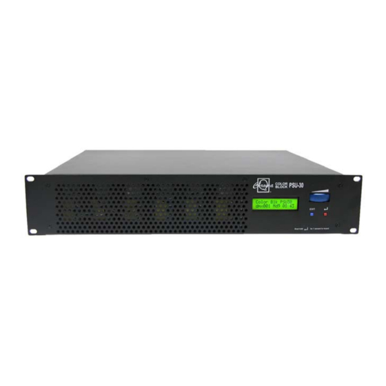
The Color Block PSU-30 is a 2U 19" rack mounted unit that supplies power and data to a maximum of 30 Color Block
DB4 or Color Block 2 LED fixtures through 6 XLR4 outputs. It can be controlled in 16 modes via ANSI E1.11 USITT
DMX 512-A, or can operate independently as a standalone system.
For the purpose of clarification, the Color Block DB4 is a fixture that contains 4 cells, with each cell comprising of 3
LEDs; the Color Block 2 is a fixture that contains 48 high output LEDs set into 12 single-optic RGBA clusters that are
grouped into 4 cells.
Note: To ensure proper functionality, Date/Time must be set before operation. Look Store will function when
Date/Time are set. Time is reset when battery is replaced or when the PSU-05B is reset.
2. Cabling
1.
Install the proper male connector to the trailing lead and connect power with input of 100-240V, 50-60 Hz.
2.
Connect input data ANSI E1.11 USITT 512-A from an external source or lighting control console through a male
XLR-5. A pass through connection is available on the female XLR-5.
3.
Connect power and output data through 6 individual female XLR-4 to the Color Block DB4 or Color Block 2
fixtures. A maximum of five daisy-chained Color Block fixtures can be connected to each XLR4 output. Return
lines are not required but the total length of each chain must not exceed 60m/~200ft.
Note: : : : See diagram in full User Manual.
3. Control Menu
The control menu items are accessed via the LCD display with the following controls:
Right hand button (red) = Enter (hold for 2 seconds to save)
•
Left hand button (blue) = Exit without saving
•
Wheel = Adjusts values or scrolls through menu items
•
Menu Options
Function
DMX Address
To set DMX start address, press Enter, turn wheel to adjust DMX start address, press Enter for 2
seconds to save
Control Mode
There are 10 DMX controlled modes for the Color Block DB4 system (CB1) and 16 DMX controlled
modes for the Color Block 2 system (CB2). Go to "System" and select either "CB1" or "CB2". There
are 3 grouping options (Individual, Block, All) with 3 control options for each (FX, HSI and RGB):
Mode
Ch
Group
1
67
Variable
2
60
Cell
3
60
Cell
4
21
Block
5
15
Block
6
15
Block
7
9
All
8
3
All
9
3
All
10
80
Cell
11
80
Cell
12
20
Block
13
20
Block
14
4
All
15
4
All
16
1
Any
When DMX is Lost
If DMX is not detected press Enter, turn wheel to selection, press Enter for 2 seconds to save. Off –
will snap to off; Hold – will hold last valid DMX state; Trig – will default to Time Trigger operation;
Look 1-42 – will snap to the Look of your choice
Color Block PSU-30 Quick Start Guide V1.0
System: CB1
System: CB2
7FX + 20xHSI
7FX + 20xHSI
20xHSI
20xHSI
20xRGB(w/ *Magic Amber)
20xRGB(w/ *Magic Amber)
6FX + 5xHSI
6FX + 5xHSI
5xHSI
5xHSI
5xRGB(w/ *Magic Amber)
5xRGB(w/ *Magic Amber)
6FX + HSI
6FX + HSI
HSI
HSI
RGB(w/ *Magic Amber)
RGB(w/ *Magic Amber)
Not Available
20xRGBA
Not Available
20xRGBI(w/ *Magic Amber)
Not Available
5xRGBA
Not Available
5xRGBI(w/ *Magic Amber)
Not Available
RGBA
Not Available
RGBI(w/ *Magic Amber)
Look Select
Look Select
Look Store
There are 42 internal FX Looks (1-9 are preset). To replay a Look, press Enter and scroll through
the Looks. 2 ways to record or edit a Look:
Simple, with DMX console: set to Mode 1. Use DMX console to adjust the internal FX engine.
•
Scroll to Look Store - press Enter, scroll to desired Look location and press Enter for 2
seconds to save.
Advanced, standalone: (To edit or record without a DMX console, please see the full User
•
Manual available at www.ac-et.com)
Time Triggers
Press Enter and scroll to Time Trigger – press Enter. Press Enter to toggle between Day, Hour (24),
Minutes and Look to be triggered - adjust setting with scroll wheel. Time Triggers will occur on all
7 days unless specified. The triggers will be activated when the mode "When DMX is Lost" is set to
Trig.
Set Day and Time
Press Enter. Press Enter to toggle between Day, Hour (24) and Minutes, scroll wheel to adjust and
press Enter for 2 seconds to save.
Displ Backlight
To set LCD backlight to go off after 5 seconds, press Enter and scroll wheel to On (permanently) or
Off (after 5 seconds) and press Enter for 2 seconds to save setting.
Reset to Default
Press Enter for 2 seconds to reset all menu items to factory defaults: DMX address = 001, Control
Mode = 1 (67 channels HSI+FX), DMX Lost = Hold, Looks = default, Display = On, Frequency =
360, System = CB2
To set PSU-05B for the Color Block DB4 (CB1) or the Color Block 2 (CB2) system press Enter, scroll
System
wheel to select CB1 or CB2, press Enter for 2 seconds to save.
Frequency
360, 600, 1200 and 2400 frequency settings available for the LED scan rate to be synchronised
with the video camera. Press Enter, scroll wheel to select frequency, press Enter for 2 seconds to
save.
Sync Mode
Press Enter and use the scroll wheel to select Master or Slave. Press Enter for 2 seconds to save
settings.
Variable
Cell
Block
Group
Group
Group
Mode
1
2
3
4
5
Ch1
Group
H-1 R-1
Speed
H-1 R-1
Ch2
Speed
S-1 G-1
Fan
S-1 G-1
Ch3
Fan
I-1
B-1
Range
I-1
Ch4
Range
H-2 R-2
Step
H-2 R-2
Ch5
Step
S-2 G-2
Int. FX
S-2 G-2
Ch6
Int. FX
I-2
B-2
Int.Fan
I-2
Ch7
Int.Fan
H-3 R-3
H-1
H-3 R-3
Ch8
H-1
S-3 G-3
S-1
S-3 G-3
Ch9
S-1
I-3
B-3
I-1
I-3
Ch10
I-1
H-4 R-4
H-2
H-4 R-4
Ch11
H-2
S-4 G-4
S-2
S-4 G-4
Ch12
S-2
I-4
B-4
I-2
I-4
Ch13
I-2
H-5 R-5
H-3
H-4 R-5
Total
67
60
60
21
15
4. Further Information
Please refer to the Chroma-Q Color Block PSU-30 manual for more detailed information. A copy of the manual can be
found at the Chroma-Q website – www.chroma-q.com – under Support.
Color Block PSU-30 Quick Start Guide V1.0
All
Cell
Block
Group
Group
Group
6
7
8
9
10
11
12
13
Speed
H-1 R-1 R-1
R-1 R-1
R-1 R-1
Fan
S-1 G-1 G-1
G-1 G-1
G-1 G-1
B-1
Range
I-1
B-1 B-1
B-1 B-1
B-1 B-1
Step
A-1
I-1 A-1
I-1 A-1
Int. FX
R-2
R-2 R-2
R-2
B-2
Int.Fan
G-2
G-2 G-2
G-2
H-1
B-2
B-2 B-2
B-2
S-1
A-2
I-2 A-2
I-2
B-3
I-1
R-3
R-3 R-3
R-3
G-3
G-3 G-3
G-3
B-3
B-3 B-3
B-3
B-4
A-3
I-3 A-3
I-3
R-4
R-4 R-4
R-4
and so on up to:
15
9
3
3
80
80
20
20
All
Group
14
15
R-1
G-1
B-1
I-1
4
4