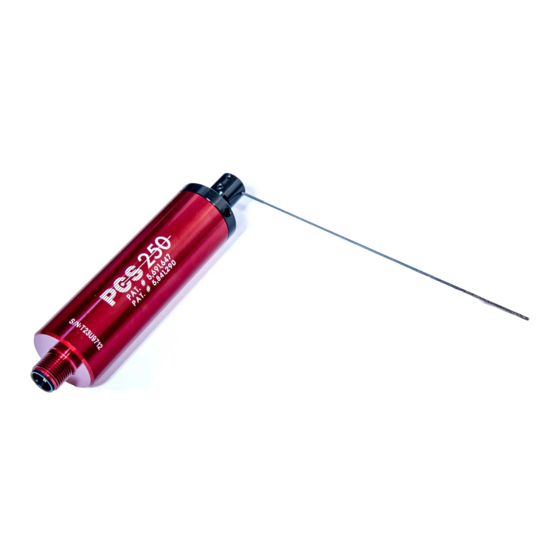
Allora Positive Contact PCS-250 Manual de instrucciones de instalación - Página 7
Navegue en línea o descargue pdf Manual de instrucciones de instalación para Accesorios Allora Positive Contact PCS-250. Allora Positive Contact PCS-250 12 páginas.

ESD/EMF PROTECTION: The TCU is a microprocessor based unit. When mounting the TCU
in the machines electrical cabinet avoid placing it near sources which might produce ESD
(electro static discharge), or EMF ( electro magnetic frequencies ), such as large motor
starters or high current devices. ESD/EMF may interfere with the units operation.
The cable supplied with the sensor is fully shielded. The preferred installation method is to
connect the sensor cable directly to the TCU. If your installation requires connecting the
sensor to the TCU via a junction box/terminal strip, avoid wiring near EMF sources.
The distance of the sensor connection to the TCU should not exceed 50m (165').
Special length shielded cables are available upon request.
Below is a basic wiring diagram for 24VDC and 115VAC machine control voltages.
For any questions or installation assistance contact 1-855-866-5911.
BASIC WIRING DIAGRAM TCU-250/24VDC
SENSOR
24VDC
TEACH PB
+
-
POWER
24VDC
CW
TIME
LO
NL
FAULT
OUTPUT
RESET PB
START SW
2 A CONTACT
FAULT OUTPUT TO PLC
INPUT, SWITCH ETC.
OK OUTPUT TO PLC
INPUT, SWITCH ETC.
TCU Installation Guide
COMMON
OK
TEACH
FAULT
CCW
1
NC
L
NC
L
2
ON
C&K SDA04
3
HI
1
2
3
4
RL
NO
M
NO
M
OK
START
OUTPUT
115V 24V
BASIC WIRING DIAGRAM TCU-250/100-240VAC
115 VAC
-V
+V
OUTPUT
24VDC 0.6A
15W
DC ON
V.ADJ
INPUT
50/60Hz
100-240 VAC 0.3A
N
L
FAULT OUTPUT TO PLC
INPUT, SWITCH ETC.
SENSOR
TEACH PB
+
-
POWER
24VDC
OK
TEACH
FAULT
CW
CCW
1
NC
L
NC
L
TIME
2
ON
C&K SDA04
3
LO
HI
1
2
3
4
NL
RL
NO
M
NO
M
FAULT
OK
START
OUTPUT
OUTPUT
115V 24V
RESET PB
START SW
2 A CONTACT
OK OUTPUT TO PLC
INPUT, SWITCH ETC.
Page 6
COMMON
