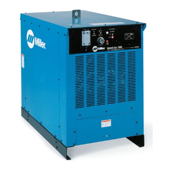
Miller Subarc DC 1000 Manual del usuario - Página 32
Navegue en línea o descargue pdf Manual del usuario para Generador portátil Miller Subarc DC 1000. Miller Subarc DC 1000 48 páginas.

4-1. Front Panel Controls (Non-CE Models)
1
Output Control Switch
For weld output, place switch in On position.
For remote control of output, make connec-
tions to terminal strip TE3 or Remote 14 re-
ceptacle (see Section 2-10) and place switch
in Remote position.
2
A/V (Amperage/Voltage) Control Switch
For front panel control, place switch in Panel
position and use the A/V Adjust control.
Y Turn Off power before connecting re-
mote device.
OM-2221 Page 28
SECTION 4 – OPERATION
For remote control, connect remote device to
terminal strip TE3 or Remote 14 receptacle,
and place switch in Remote position. Remote
control provides full range of unit output re-
gardless of A/V Adjust control setting
3
Pilot Light
4
Power Push Button Switch
.
The fan motor is thermostatically
controlled and only runs when cooling is
needed.
1
2
6
5
High Temperature Shutdown Light
Lights if welding power source overheats.
6
A/V (Amperage/Voltage) Adjustment
Control
Use control to select weld voltage or amper-
age. Control may be adjusted while welding.
Numbers on scale are for reference only.
7
CC/CV Switch (Mounted Inside Access
Area)
Place switch in desired position.
3
5
CC
CV
7
Y Turn Off welding power
source before opening ac-
cess door to change switch
position.
Ref. ST-175 086 / Ref. ST-801 882-A
4
