Chromalox 2110 Manual de instrucciones - Página 13
Navegue en línea o descargue pdf Manual de instrucciones para Controlador de temperatura Chromalox 2110. Chromalox 2110 20 páginas.
5. Control and Alarm Operation
Control Operation
The 2110 is shipped from the factory with PI (propor-
tional/integral) control. Proportional control actually
determines the percent of heat needed to control the
process. The factory setting for the Proportional Band
is 25°F and the Automatic Reset (Integral) is set at 0.1
repeats/minute. These settings will control many pro-
cesses without any changes to the controller. If the
process is unstable or too sluggish, the Proportional
Band and Automatic Reset can be changed in the
menu configuration.
Tuning PI Control
Adjust Proportional Band - The objective of the pro-
portional band adjustment is to find the proportional
band setting at which the process temperature stabi-
lizes and does not oscillate. If the temperature display
is oscillating, increase the Proportional Band (doubling
the value) until the temperature display has stopped
oscillating. To establish a quick response to control up-
sets, adjust for the smallest band that provides stable
control (does not oscillate). Note: The temperature at
this point may not be at set point, but will be stable.
Adjust Automatic Reset (Integral) - The Automatic
Reset (Integral) automatically removes the offset be-
tween process temperature and set point. If the pro-
cess is too sluggish in approaching set point, double
the automatic reset. Too much automatic reset will
make a process unstable.
Cycle Time - Cycle time setting determines how often
to switch the output to the heater. For example, if the
cycle time is 1 second and the 2110 needs a 75% out-
put, the output will be on for 3/4 of a second and off 1/4
of a second. Units with relay control outputs (R1 or R3)
are shipped with a 30-second cycle time. Units with
solid state relays or solid state relay drives (S0, S1, S2,
or V0) are shipped with a 1-second cycle time.
Alarm Operation (optional)
An alarm relay output is optional on the 2110. An alarm
can help protect the process when a too high or too
low temperature occurs.
High Alarm: This alarm is a high absolute alarm that
actuates when the process temperature is equal to or
greater than the alarm set point. For example, if the
high alarm set point is 500°F, the alarm will always ac-
tuate when the process temperature reaches 500°F.
Low Alarm: The low absolute alarm actuates when the
process temperature is equal to or less than the alarm
set point. The low alarm features a power-up inhibit to
prevent undesirable alarms during process start up. Af-
ter the unit reaches control set point, the low alarm will
respond.
Alarm Dead Band: The alarm relay de-energizes (re-
sets) when the temperature crosses out of the alarm
dead band. For example, if the high alarm is set to
500°F and the alarm dead band is 5°F, the alarm condi-
tion will not reset until the process temperature reach-
es 495°F.
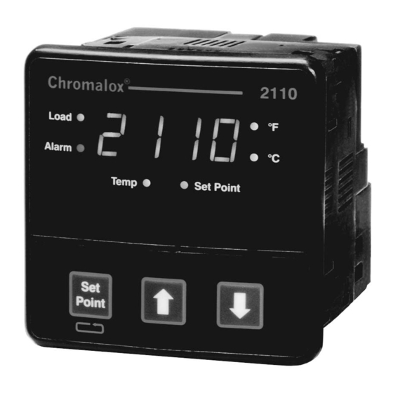
To enable the alarm relay, select either high or low alarm
type and set the alarm set point. An alarm condition is
indicated when the Alarm light to the left of the display
illuminates. Alarm type, set point, and dead band are
selectable through the user configuration interface.
11