AQUAPHOR RO-102S IL Manual del usuario - Página 6
Navegue en línea o descargue pdf Manual del usuario para Sistemas de filtración de agua AQUAPHOR RO-102S IL. AQUAPHOR RO-102S IL 16 páginas. Reverse osmosis system

During transportation, the component parts are
located under the top lid. To open the lid, please
turn the three plastic latch screws on the cover
90 degrees counterclockwise (figure 2).
Figure 2. How to open the top lid
4. RO design
and operation principles
• RO housing (1) consists of an upper plate,
with four collectors fixed onto it, to place the
replacement cartridges and the RO-hydro
automatic unit RO. The upper lid comes with
a decorative cover, fixed in place with three
plastic latches. An integral part of the RO
housing is the treated water storage tank (6).
Treated water goes into the storage tank upon
exiting the membrane cartridge. This storage
tank ensures availability of the required amount
of filtered water always.
• Preliminary water treatment block (2, 3) includes
replacement filter cartridge includes replace-
ment filter cartridge K5 (for RO-101S, RO-102S,
Aquaphor RO-101S IL, Aquaphor RO-102S IL) (3)
or cartridge K1 (for RO-101S EU, RO-102S EU)
(3) and K2 (2). The preliminary water treatment
block removes any impurities that can damage
membrane cartridge, such as ferric hydroxide
and active chlorine.
• Reverse Osmosis membrane block (4) includes
the replacement membrane cartridge Aquaphor
RO-50S (for RO-101S, RO-101S EU, Aquaphor
RO-101S IL) or Aquaphor RO-100S (for RO-102S,
RO-102S EU, Aquaphor RO-102S IL) and puri-
fies water by removing organic compounds,
non-organic compounds, and salts while sof-
tening water.
• Water conditioning block (5) includes the min-
eralizing cartridge K7M (for RO-101S, RO-102S,
Aquaphor RO-101S IL) or K7BM (for RO-101S
EU, RO-102S EU, Aquaphor RO-102S IL). The
water conditioning block eliminates unwanted
odors and flavors from water while mineralizing
the water.
6
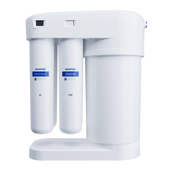
Figure 3. RO main components
1 – RO housing assembly;
2, 3 – Preliminary water treatment block;
4 – Reverse Osmosis membrane block;
5 – Water conditioning block;
6 – Storage tank
1
6
2
3
3
5
How RO works
The water coming from the cold water mains
enters RO and passes through the preliminary
water treatment block. From there, water enters
the Reverse Osmosis membrane block via the
automatic check valve. The unit housing the
membrane cartridge has two outlets: the treated
water outlet and the drain water outlet. On its
way to the drain, the water will also pass through
a flow restrictor. The flow restrictor flushes the
drain water that goes down the drain.
The treated water enters the storage tank that
has a built-in membrane. This separates the tank
into two chambers: storage and technical. The
storage chamber contains the fully purified drink-
ing water, while the technical chamber contains
water from the mains. As clear water collects,
water from the mains is forced from the techni-
cal chamber into the drain, also preventing the
accumulation of clear water. When the storage
tank is full, the automatic check valve cuts off
the water intake into RO.
4
1
4
2
