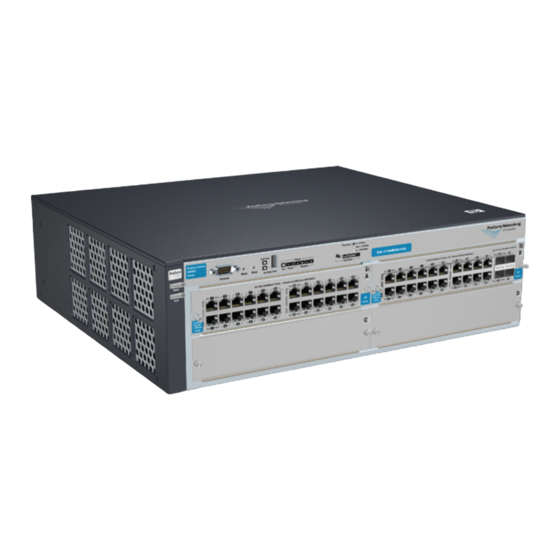
HP ProCurve 4208vl-64G Manual de instalación - Página 6
Navegue en línea o descargue pdf Manual de instalación para Interruptor HP ProCurve 4208vl-64G. HP ProCurve 4208vl-64G 13 páginas.

9/18/2020
Item Number
Item Number
1
NOTE:
The 4200vl Switch Series does not have a power switch. They are powered onwhen the power cord is connected to the
switch and to a power source.If installation requires a different power cord than the one supplied with the switch.
2. Check the LEDs on the switch and on each of the switch modules.
If the LED display is different than what is described, especially if the Fault LED stays on for more than approximately 120 seconds
or it startsflashing, the self test has not completed correctly. Refer to ProCurve 4200vl Switch Series troubleshooting page.
here to go to HPE ProCurve 4200vl Switch Series Troubleshooting
Figure 5: Switch LEDs
Item Number
1
2
When the switch is powered on, it performs its diagnostic self test. The entiredownload, initialization, and self test process can take up to 2
minutes for afully loaded chassis, depending on the number and type of modules installedin the switch.
LED Behavior:
During the self test:
Initially, Power and Fault, and all the switch chassis LEDs are ON. Then, after approximately 30 seconds, all the module LEDs go
ON as the modules receive power and code is downloaded to them, the Fault LED goes off,and the chassis LEDs go off except
Power, Self Test, Fan Status, and PowerStatus.
When the download of code to the modules is completed, the module LEDs go off. User may see each port LED go ON briefly, in
sequence, as theport is tested.
For the duration of the self test, the Self Test LED stays ON.
When the self test completes successfully:
The Power LED stays on, and the Status LEDs on the switch chassis stay on for the devices installed: one for each switch module
installed, one for each power supply installed, and one for all the fans.
The Fault and Self Test LEDs are off.
The port LEDs on the switch modules go into their normal operational mode:
If the ports are connected to active network devices, the Link LEDsstay on and the Mode LEDs behave according to the mode
selected.In the default mode (Activity), the Mode LEDs should flicker showing network activity on the port.
If the ports are not connected to active network devices, the LED swill stay off.
top
Mount the switch
After the modules and optional power supply are installed and user have verified the switch passes self test, user are ready to mount the
switch in astable location. The 4200vl Switch Series can be mounted in these ways:
In a rack or cabinet
On a horizontal surface
On a wall
Rack or cabinet mounting
The Switch 4200vl Series is designed to be mounted in any EIA-standard 19 in telco rack or in an equipment cabinet such as a server
cabinet. If user are installing the switch in an equipment cabinet.
1. Use a #1 Phillips (Cross-head) screwdriver and attach the mounting brackets to the switch with the included 10 mm M4 screws.
For the 4204vl, 4202vl-48G, and 4202vl-72 Switch, each bracket is attached with two screws, and for the Switch 4208vl and its
bundles each bracket is attached with three screws as shown in the illustrations below.
Figure 6: Attaching brackets to a 3U chassis
HPE 4200 vl Switch Series - Installation
Description
Switch module LEDs:Link and Mode LEDs for each port
Switch chassis LEDs
Description
Description
Power socket
.
Click
6/12
