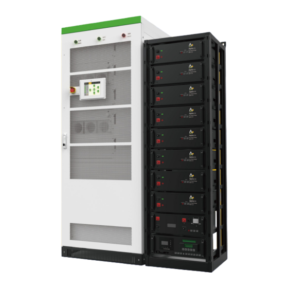
Alpha ESS Storion-T100 Manual de instalación - Página 6
Navegue en línea o descargue pdf Manual de instalación para Almacenamiento Alpha ESS Storion-T100. Alpha ESS Storion-T100 18 páginas. Energy storage system

PRODUCT DESCRIPTION
Table 2 Composition of the PCS
Position Designation
1
Indicator lights
2
EPO (Emergency Power Off)
3
Touch Screen
4
PCS-DC (1~2 module(s))
5
PCS-AC (1~2 module(s))
6
STS module
7
Wiring terminal
8
AUX power supply switch
9
SPD switch
10
AC breaker (Grid)
11
AC breaker (Load)
12
Battery switch
13
PV DC switch
Note:
Components 7 Wiring Terminal, 8 AUX power supply switch, 9 SPD switch can be seen after
unfold the dam-board.
3.3.1.3 Technical Parameters
Table 3 Technical parameters of the PCS
No.
Item
AC Side Data (off-grid)
1
AC nominal output power
2
AC max. power
AC output voltage
3
Voltage range
4
AC output current
5
6
AC connection
AC frequency
7
8
Output THDu
9
AC PF
Overload capability
10
DC Data(Battery Side)
11
DC voltage range
12
One-Way maximum input Current
13
Max. DC power
Description
50KW 1 set; 100KW 2 sets
50KW 1 set; 100KW 2 sets
Switching device; Only for the models with STS
Digital input and digital output
Storion-T50-INV
Storion-T100-INV
50 kW
100 kW
55 kW
110 kW
400 Vac (± 10% configurable)
400 V ± 10 %
72 A (max. 79 A)
144 A (max. 159 A)
3-phase and 4-wire system
(including transformer)
50 Hz / 60 Hz
<2 %
Listed: 0.8~1 leading or lagging (Load-depend)
Actual: 0.1~1 leading or lagging (Load-depend)
100%~110% long-term;
110%~120% 1min;
120%~150% 200ms;
250 – 520 V
150 A
300 A
50 kW
100 kW
07
08
PV Side Data
14
PV voltage range
PV DC max. current
15
(in case of completely consumption)
17
Max. PV power
General Data
18
Max efficiency
19
Dimensions (W x H x L)
20
Weight
21
Altitude
22
Ingress protection
23
Noise
24
Operation temperature
25
Cooling concept
Humidity
26
Communication interfaces
27
3.3.1.4 Emergence Stop Switch
The converter stops working immediately after pushing the button.
If you want to restart the converter, please proceed in the following order:
A.
Conduct clockwise rotation on the emergency stop switch and then loosen the
locking status.
B.
Push the AC breaker into "OFF" position, then turn the AC breaker "ON".
C.
Launch the machine and operate it as required
3.3.2 Battery System
Item
Description
1
Nominal discharge power
Energy storage capacity
2
3
Continuous discharge current
4
Direct voltage
5
Communication interface
520 – 900 V (MPPT: 520~800 V)
192 A
100 kW
95.5%
800 x 2160 x 800 mm
520 kg
3000 m
IP20
70 dB
-25 °C ~ +50 °C (De-rating over 45°C)
Forced Air
0~95% (Non-Condensing)
Ethernet‚RS-485‚ CAN
Table 4 Battery system parameters
Parameter
50 kW / 100 kW
According to the project
situation
1C (continuous)
250 ~ 520 V
RS485, CAN2.0
PRODUCT DESCRIPTION
384 A
200 kW
750 kg
Remark
Ambient temperature
is 30°C, measured at DC side
