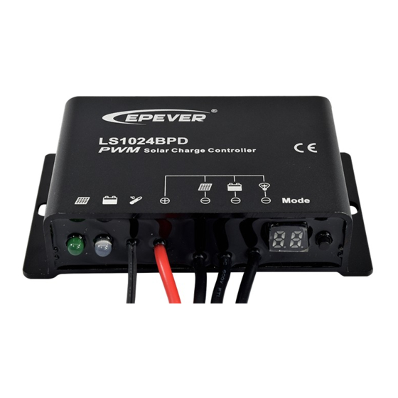
Epever LS BPD Series Manual de inicio rápido
Navegue en línea o descargue pdf Manual de inicio rápido para Controlador Epever LS BPD Series. Epever LS BPD Series 2 páginas. Solar charge controller

LS BPD series Solar Charge Controller
1. Safety Information
Read all of the instructions in the manual before installation.
DO NOT disassemble or attempt to repair the controller.
Install external fuse or breaker as required.
Do disconnect the solar module and fuse/ breakers near to battery before installing or
moving the controller.
Power connections must remain tight to avoid excessive heating from a loose
connection.
Only charge batteries that comply with the parameters of controller.
Battery connection may be wired to one battery or a bank of batteries.
Risk of electric shock, the PV and load can produce high voltages when the controller is
working.
2. Overview
Thank you for selecting the LS BPD series solar charge controller. The LS-BPD controller
is a waterproof PWM charge controller that adopts the most advanced digital technique.
The multiple load control modes enable it can be widely used on solar home system, field
monitoring, traffic signal, solar street light, solar garden lamp, etc.
It's an easy operation and cost efficient controller featured as:
3-Stage intelligent PWM charging:Bulk, Boost/Equalize, Float
Support 3 charging options: Sealed, Gel, and Flooded.
Programmable LVD and main parameters via digital tube and button
Multiple load control modes
Extensive Electronic protection
Battery temperature compensation function.
IP67 waterproof degree
3. Product Features
①
②
④
③
⑤ ⑥
Figure 1 Product Feature
Mounting hole Φ5
①
②
Charging status LED indicator
③
Battery status LED indicator
④
*
Temperature Sensor
⑤
PV、Battery and Load positive wire
*
If the temperature sensor short-circuited or damaged, the controller will be
charging or discharging at the internal temperature of device.
4. Wiring
Figure 2 Connection diagram
(1) Connect components to the charge controller in the sequence as shown above and pay
much attention to the "+" and "-". Please don't insert the fuse or turn on the breaker during
the installation. When disconnecting the system, the order will be reserved.
(2) After power on the controller, check the battery LED indicator on the controller, it will be
on solid green. Otherwise please refer to chapter 8. Always connect the battery first, in
BEIJING EPSOLAR TECHNOLOGY CO., LTD.
⑦
⑨
⑩
⑧
⑥
PV negative wire
⑦
Battery negative wire
⑧
Load negative wire
⑨
Digital tube
⑩
Button
1
Tel:+86-10-82894112 / 82894962
order to allow the controller to recognize the system voltage.
(3) The battery fuse should be installed as close to battery as possible. The suggested
distance is within 150mm.
5. LED Indicators
Indicator
Color
Status
Green
On Solid
Green
Slowly Flashing(1Hz)
Green
Fast Flashing(4Hz)
Green
OFF
Green
On Solid
Green
Slowly Flashing(1Hz)
Green
Fast Flashing(4Hz)
Orange
On Solid
Red
On Solid
Red
Fast Flashing(4Hz)
Red
On Solid
Red
OFF
Charging (green) and battery indicator (orange)
flashing simultaneously
6. Setting Operation
LED1
Radix point
Button function
The controller parameters can be set via the button:
Mode
When the load mode is Manual mode, press the button can turn
Load ON/OFF
on/off the load.
Press the button
Clear error
Press the button and hold on 5s then the digital tube will be on.
Browse Mode
Press the button to roll the item in circle.
Press the button to roll the item in the browse mode and hold on 5s
Parameter set
to enter edit parameters with the LED2 flashing. Modify the value by
Mode
pressing the button. Save the data and return to the menu until the
LED2 stop flash.
Digital Tube Display
The reference of LED for parameter and setting value is shown in the table
LED1
Item
Battery type
Low voltage disconnect
voltage①
Load set
Light ON/OFF threshold
voltage③
Light ON+Time mode1:Time1
Light ON+Time mode2:Time2
①
Low Voltage Reconnect Voltage =Low Voltage Disconnect Voltage+0.5V/12V(x2/24V).
②
Radix point of LED segment display indicate the value added "10", for example 0.=10, 4. =14.
③
For day/night detection, load will be automatically turned on/off when PV voltage is
below/above threshold voltage.
LED Code
Code
Over discharged
Under voltage
①
Load over load
Load short circuit
The radix point of LED1 lighting up
indicates that load is ON.
Oppositely, load is OFF.
①When load current reaches1.02-1.05 times 1.05-1.25 times, 1.25-1.35 times and
1.35-1.5 times more than nominal value, controller will automatically close loads in 50s,
Website:www.epsolarpv.com/www.epever.com
Instruction
PV connection normal but
low voltage(irradiance) from
PV, no charging
In charging
PV reverse polarity
No PV voltage(night time) or
PV connection problem
Normal
Full
Over voltage
Under voltage
Over discharged
Battery Overheating
Load ON
Load OFF
Controller overheating
Button
LED2
Note
LED2
Value
Default
Range
1:Sealed
2:Gel
3:Flooded
10.6V-12.0V Unit
②
value=0.1V(x2/24V)
0:Light ON/OFF
1:Light ON +Timer
2:Manual Mode
3:Output mode
4:Test mode
1-17V(x2/24V)
②
0-14H,Unit value= 1H
②
0-14H,Unit value= 1H
②
Detail
If fault and working state on left appear,
corresponding code will be displayed.
Several states occur at the same time,
these code will be displayed circularly
(interval 1s). Only one state occurs, the
code flashes per 1s. You can enter
setting mode and set parameters despite
the error shows
Load state (radix point) will conceal
during fault displaying and parameter
setting
2
