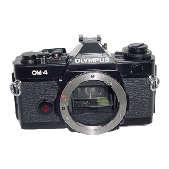
Olympus OM-4 Manual de solución de problemas - Página 2
Navegue en línea o descargue pdf Manual de solución de problemas para Cámara digital Olympus OM-4. Olympus OM-4 24 páginas.

If battery voltage is below 2.65v or there are no
batteries, IC-102 does not release the opening curtain.
For low voltage lockout situations, there is a Reset
Circuit which resets the CPU when voltage goes above
2.90v or new batteries are installed. This feature
eliminates the manual reset function necessary on OM-2
models. IC-102 will wait to see if voltage rises to 2.90v, If
it does, the release cycle continues.
Setting the speed ring to mechanical "60" or "B"
overrides IC-102's control so the shutter is released by the
mirror.
Exposure Control
Here is a list of exposure modes, all of which are
aperture priority or manual.
1, Automatic by average light measurement. This is
essentially the same off-the-film method as used by
OM-2 and OM-10.
2 Automatic by spot measurement. Unlike the
OM-2, exposure is calculated in advance,
3. Automatic by memory, wherein an exposure is
repeated on all subsequent exposures for up to an
hour.
4. Manual by average light measurement, which is
similar to match needle only with an LCD bar graph
instead of a needle.
5. Manual by spot light measurement.
6. Any mode using spot measurement can be witl
highlight or shadow compensation.
7. Off-the-film flash exposure control.
Where and how all of these options are used is the
operator's province. Ours is to know how each mode
functions from an electrical standpoint.
1. Automatic by Average Light
ASA is the only exposure component needed in
advance for this exposure mode. Subject brightness and
aperture are still measured prior to exposure, but are only
used for display purposes.
As the mirror rises and the ICs prepare for exposure,
voltage to one input of comparator CP-M inside IC-102
is set to a value based upon ASA. The second input is
connected to the integration output from pin 10, IC-103.
Because IC-102 has not signaled IC-103 to start
integration, voltage at the second input is set low.
Now the mirror is up and the averaging light
photodiode (SPD-A) is looking at the opening curtain
which is painted to have reflectivity equal to film. IC-102
— after checking battery voltage — fires magnet MG-1 to
release the opening curtain. Trigger Switch SW-103
opens to signal movement of the curtain, (There is an
adjustable delay circuit with C-101 and VR-102 to set slit
width at fast speeds.) Light from the subject is focused on
the opening curtain (and later the film) through the
OLYMPUS OM-4, PAGE 2
stopped-down lens, A portion of this light reflects back to
the photodiode on IC-103,
IC-102 initiates integration of reflected light with t i m e
(the equivalent of exposure) with a signal from pin 80 to
pin 14, IC-103. Voltage on the integrator's output begins
to increase at a rate proportional to light intensity at the
film plane. The same voltage appears on the second input
of comparator CP-M. When voltage levels at both inputs
of CP-M are equal, exposure for that particular film is
correct, CP-M switches states and the voltage at pin 57,
IC-102 falls to zero.
Pin 57 is connected to transistor Q-202 on the shutter
board, Q-202 stops conducting current through magnet
MG-2 which has been latching the closing curtain and the
exposure ends. As the mirror returns, SW-101 opens to
reset the ICs into metering mode,
2. Automatic by Spot Measurement
With the mode set to "Auto," pressing the "Spot"
button changes exposure control from off-the-film to a
type using digital memory. Part of the light from the
portion of subject covered by the focusing area of the
viewfinder screen is reflected to the spot photodiode
(SPD-S). The CPU controls which photodiodes are used
according to mode. SPD selection is through pins 6 and
7, IC-103.
IC-102 converts BV voltage along with aperture and
ASA data to a binary code, then sends the information to
the CPU inside I C-101. Subject brightness at the moment
the Spot Button was pressed is stored; however, changes i
aperture and ASA will still affect auto shutter speed.
Each time the Spot Button is pressed (before exposure) a
new spot reading is added to the exposure calculation and
averaged with previous readings. The process continues
until a total of 8 spot readings are taken, then subsequent
measurements cause the first readings to drop off.
When the release button is pressed and the mirror
closes SW-101, the last exposure indicated by the bar
graph in the display is stored in IC-101's digital memory,
The CPU sends an exposure program to IC-102 telling it
to ignore IC-103's off-the-film integration and instead to
set up its own integration. Capacitor C-104, connected to
pin 44, IC-102, will be charged by a constant current.
Magnitude of the current is set proportional to the
shutter speed calculated by the CPU. Binary speed
information is decoded by IC-102 (DAC) to analog
voltages. Faster speeds call for higher currents.
When the Trigger Switch opens, current from IC-102
begins to charge capacitor C-104, Voltage on C-104 is
also connected to one input of comparator CP-M, the
same as used for off-the-film exposure. When the voltage
reaches a preset level equal to that on CP-M's other
input, the comparator switches states to turn off Q-202
and release the closing curtain,
As the mirror returns and SW-101 opens, the ICs are
reset to auto exposure using average light readings.
