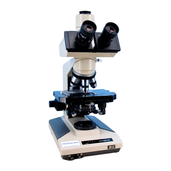
Olympus B2-BDT Manual de solución de problemas y ajuste - Página 26
Navegue en línea o descargue pdf Manual de solución de problemas y ajuste para Microscopio Olympus B2-BDT. Olympus B2-BDT 46 páginas. For electrical base

B.
TROUBLESHOOTING
(B2-BDS-2)
No. B-9
Replace the UYPC65.
Is
power
supplied normally?
Are
the UYPC64 and
the
primary
voltage selector switch SW103
conducting?
YES
NO
0
+
Replace the
spark gap RC102
and
RC103.
Is
power supplied
normally?
YES
'
(EtD)
0
NO
@
Measure
the voltage
between SW101
QJ
and JlOl
!m
with a
mul timeter. Normal
if the
voltage equal to the AC line
voltage
is applied.
Abnormal if not.
The terminals are
covered with a tube.
Tear the tube or
puncture it
with
a
needle for the
measurement.
®
Measure
the
voltage between SWlOl
CD
and
JlOl
!m
with a mul timeter. Normal
if the voltage
equal to the AC line
voltage
is applied.
Abnormal if not.
The terminals
are covered with a tube.
Tear the tube
or puncture it with a
needle for the
measurement.
Q)
Monitor
the
waveform between J201
CD
and
J201
rn
with an oscilloscope.
Normal if the
waveform is almost as
shown
below.
Abnormal if not.
*
When
the light
intensity
control
lever is moved
from "Min" to "Max"
Is the output of UYPC64
G)
position,
the
high level
cycle
of
normally?
YES
NO
Replace
the UYPC64.
Is
power
supplied normally?
YES
t
(E!o)
(>NO
Replace the transformer
TlOl.
a
signal is
prolonged.
G)
Monitor
the
waveform between J301
ITJ
and J301
CD
with an oscilloscope.
Normal
if the
waveform with the AC
phase controlled as shown below is
obtained.
Abnormal
if not.
*
When the light
intensity control
lever is adjusted, the
phase angle
is
varied.
