Olympus CH10 Manual de reparación - Página 19
Navegue en línea o descargue pdf Manual de reparación para Microscopio Olympus CH10. Olympus CH10 31 páginas. Biological microscope
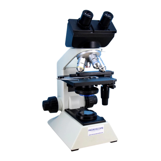
CH10/CH20
No.
Parts name
•
BODY
‚
CLIP HOLDER 3PUK2X8SA (*2)
ƒ
SPACER
„
CLIP
...
NUT
†
SPRING
‡
LATERAL
GUIDE-3
ˆ
LATERAL
GUIDE-1
‰
WIRE GUIDE
(2 pcs.)
±
CASING
1 0
±
WIRE GUIDE
1 1
(2 pcs.)
±
LATERAL
1 2
GUIDE-2
±
WIRE GUIDE
1 3
(2 pcs.)
±
CASING
1 4
±
WIRE GUIDE
1 5
(2 pcs.)
±
X-RACK
1 6
±
SPRING
1 7
C. DISASSEMBLY AND ASSEMBLY PROCEDURES
Screw
AB3X8SA (*1)
2 pcs.
3 pcs.
CSK3X8SA (*3)
3PUK2. 6X10SA (*4)
3 pcs.
SP1.6X4UO (*5)
PSTB1. 7X3SA (*6) 2
pcs.
PSTB1. 7X3SA (*7) 2
pcs.
B3SO (*9) 6 pcs.
PSTB1. 7X3SA (*8) 4
pcs.
B3SO (*10) 6 pcs.
3PUK2X6SA (*11)
2 pcs.
HWB2SA (*12) 2 pcs.
Grease
Adhesive
OT1028
OT1131
OT2008
OT2008
OT2008
OT1131
OT2008
OT2008
OT2008
OT2008
OT2008
OT2008
OT2008
OT1131
C-9
Remarks
Apply adhesive on the assembly
surface for lateral guide-1ˆ.
Apply adhesive on the screw head.
Clearance between the stage and the
clip holder: 0.2 - 0.7 mm
Mount the spacer with the round edge
side faced downwards.
Apply grease on the contact surface
with the clip holder ‚.
Apply grease on the contact surface
with the clip holder ‚.
Clip working force: 1.0 - 1.5N {100 -
150 g}
Apply adhesive on the screw head.
Apply grease on the fitting surface of
±
thinly.
wire guide
1 5
Apply grease on the balls.
Apply grease on the wire guide fitting
surface thinly.
Rotation force at assembling the X/Y-
knob: 0.2 - 0.98N {20 - 100 g}
Apply grease on the balls.
Apply adhesive on the screw head.