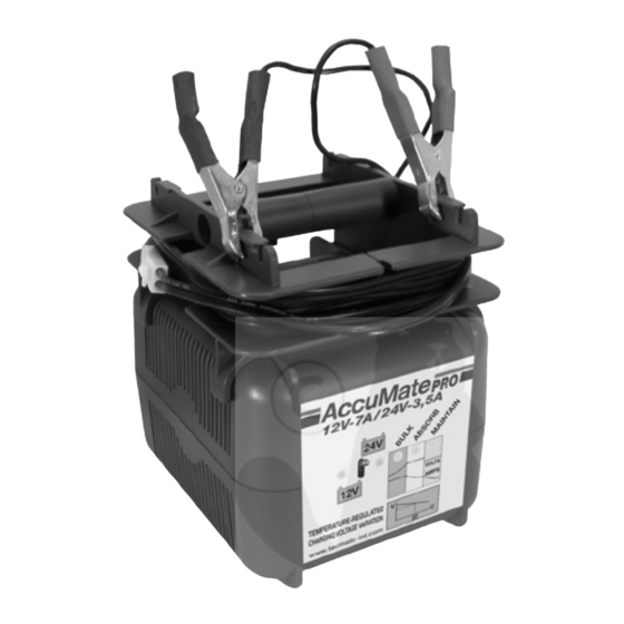
AccuMate PRO 12/24 Manual de instrucciones - Página 2
Navegue en línea o descargue pdf Manual de instrucciones para Cargador de batería AccuMate PRO 12/24. AccuMate PRO 12/24 12 páginas.

AccuMate PRO
OPERATING INSTRUCTIONS
IMPORTANT : Read completely before use.
Automatic charger for lead/acid engine-start batteries of voltage type matching the rated output voltage stated on the
charger. Not for charging dry cell or NiCad batteries.Input voltage :110-120V~.Minimum rated capacity of battery to
be charged : at 12V - 4A,10Ah; at 12V - 6A,15Ah; at 12V - 7A,17Ah; at 24V - 3,5A, 8Ah.
IMPORTANT ! If the charger has a charging output selector switch to select for 12V batteries (which have
6 cells) or 24V batteries (which have 12 cells), IT IS ESSENTIAL TO ENSURE THAT THE SELECTOR SWITCH IS
CORRECTLY POSITIONED ACCORDING TO THE VOLTAGE OF THE BATTERY TO BE CHARGED BEFORE THE CHARGER
IS CONNECTED TO IT. If not sure, contact the battery supplier for advice before connecting the charger.
WARNING ! Connecting a battery without ensuring that the charging output selection is appropriate to the
nominal battery voltage may cause a hazard resulting in the production & accumulation of dangerous explosive
gases as well as the overheating and potential destruction or even the explosion of the battery.
THIS COULD RESULT IN SERIOUS PERSONAL INJURY OR EVEN DEATH.
CARE : Protect your charger & it's leads,connectors,fuse holders,fuses & terminations from contamination
by acids and fluids, from exposure to damp and humidity, and from physical and accidental damage. Any
damage to the unit, its leads or accessory parts resulting from such contamination, exposure or damage is
NOT covered by warranty, both during use and in storage.
CONNECTIONS: An additional fused cordset is supplied with eyelets for direct connection to battery terminals and
a polarized push connector for connection to battery charger. Consult a professional service agent to permanently connect
the cordset to the battery in the vehicle.Ensure that it is positioned and restrained in such a way that it does not impede
operation of any moving part of the vehicle and will not cause any danger of electrical short circuit during the normal use
of the vehicle.Protect the polarized connector from ingress of grime and dirt.Before connecting the polarized connector
to the battery charger, ensure that :
the vehicle is stationary and not operational;
all accessories in the vehicle are
switched off ;
the polarized connector is completely dry and free of grime and dirt, and
the battery charger is not
connected to AC mains power. The fuse in the cordset is intended to protect against overheating of the cordset and/or the
battery in case of an accidental short across the cordset wires.The charger is itself electronically protected against this.
Should the fuse for any reason blow, have the cordset carefully checked and replace if necessary. Replace a blown fuse
only with a fuse of identical rating and type.
If intending to charge using the battery clips,first disconnect and remove the battery from the vehicle and place in a well-
ventilated area.Ensure that the polarised 2-pin connector is situated away from the battery. Prevent ingress of grime and
dirt to the 2-pin connector. If in any doubt concerning any of the above instructions, consult a professional service
agent for assistance. Other specialised connection accessories are available as options.Ask your dealer for details.
TEMPERATURE : This charger monitors both it's own internal temperature,which it limits automatically by current
regulation,and the surrounding ambient temperature,according to which it varies its charging output voltage parameters.
Should the internal temperature rise excessively due to restricted ventilation or extreme ambient conditions,the charging
output will be reduced automatically until the internal temperature has stabilised at a safe level.Some models of this charger
have a built-in cooling fan.Should the fan be jammed or out of order, the charger will be disabled and should be sent to
a service agent for checking and repair. The charging output voltage parameters are increased or decreased according to
decreases or increases respectively in the monitored ambient temperature,the nominal voltage parameters for each stage
of charging being set at a 20°C (68°F) datum.On removal of the ambient temperature sensor which is plugged in at the
rear of the charger, the voltage parameters will revert to their default settings as enumerated in the «Charging Procedure»
text below. For more exacting applications,the standard plug-in sensor can be removed and replaced by an optional 2m
long probe whose NTC thermistor tip when taped to the battery casing affords precise monitoring of the actual battery
temperature for optimum voltage management.Order reference AMPROTPRO2.
FUSES : The charger is electronically protected against short-circuited output and inverted connections,and sparks due
to making/breaking battery connections or accidental short-circuiting, are suppressed though not necessarily totally
absent.In addition the charger is protected by several fuses,located both externally and internally. A fuse at the AC input
protects against mains input disturbances. To replace this fuse,use a suitable coin or screwdriver to twist open the fuse
cover. An internal fuse protects against possible cooling fan malfunction.A thermal fuse acts as final protection against
transformer burn-out.Do not attempt to replace internal fuses, send the charger to an authorised service agent.Should
the input protection fuse blo w, check the input power cable and plug for damage or wear.
Replace any burnt fuse only with a new fuse of identical type and rating.
2
