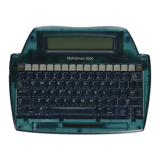
Alphasmart 3000 Instrucciones de montaje - Página 2
Navegue en línea o descargue pdf Instrucciones de montaje para PDA Alphasmart 3000. Alphasmart 3000 4 páginas.
También para Alphasmart 3000: Manual de inicio rápido (13 páginas), Manual rápido (3 páginas)

If you want to have a lock switch that lets you lock the On/Off key so it doesn't get
pressed accidentally, solder the DIP switch in the rectangle between the spaces
labelled On/Off and File 1 in the top left corner of the front of the PCB, the side
with silkscreen printing.
If you don't want to have a lock switch, find the jumper pads in the top right corner
of the unmarked back of the PCB and bridge them with a small blob of solder.
Place the connectors in pads on the back of
the PCB so that their mouths are facing
away from the center, making sure all the
pins get through. Be careful when soldering
them that you don't bridge the pins.
Carefully but firmly insert the 10-pin cable
in the corresponding connector so that its
pins face away from the PCB. Raise the latch
Fig. 2
on the 16-pin connecter, out, then upward,
and insert the 16-pin cable so its pins face towards the PCB. Close the latch and
make sure the cables aren't liable to fall out. At this point, if you wish to test the
board, skip ahead to Installing the Keyboard. You can test the key sockets by
bridging the pads with a piece of wire or metal tweezers.
Place the switches in the holes on the front of the PCB, checking each one to make
sure the pins went through without bending. The pins of MX- and Alps-style
switches should be oriented towards the top, and those of Choc switches towards
the bottom. If you are using MX- or Alps-style switches, it's recommended that you
