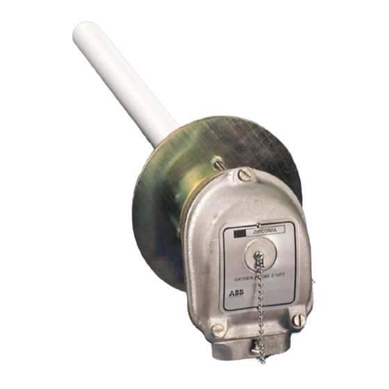
ABB ZGP2 Series Manual de instrucciones - Página 10
Navegue en línea o descargue pdf Manual de instrucciones para Equipamiento industrial ABB ZGP2 Series. ABB ZGP2 Series 16 páginas. High temperature zirconia oxygen probe

...3 INSTALLATION
3.3 Mounting – Figs. 3.7 to 3.9
The probe may be fitted horizontally or, preferably, vertically
for prolonged high temperature operation.
Mount the probe through the furnace wall using the preferred
method shown in Fig. 3.7. Ensure that a sufficiently large hole
is provided through the mounting (min. bore 42mm diameter)
to avoid damage to the probe during insertion or use.
Drill the fixing flange to suit the local fixing requirements before
assembling the probe – see Section 2.3
Caution.
To
contaminating the reference air, always ensure that the
clamp ring, fixing flange and sealing ring are fitted to the
probe as described in Section 2.3.
In applications such as high temperature incinerators, fluid
bed boilers, and ore roasters, where the level of water vapour
in the waste gases to be measured can be extremely high, it is
important that the mounting flange of the probe, including any
stand-off which may be used, is thermally insulated to
minimize condensation within the probe – see Fig. 3.7.
Condensation within the probe sheath, particularly in outdoor
installations, can be sufficient to allow water to come into
contact with the hot ceramic (zirconia) tube leading to thermal
shock and failure of the sensor. This problem is most likely to
occur on such installations where the plant is shut-down
regularly over the week-end. Additionally, take care to protect
the head of the probe from the elements in out-door
installations.
Raising the temperature of the probe as rapidly as possible will
assist in reducing the level of condensation. This is not
possible on some processes where the plant temperature is
gradually raised to the normal operating level. The
temperature rise at the head of the probe can be assisted by
having a large clearance hole in the refractory allowing hot
gases to get up to the mounting flange/stand-off – see Fig. 3.8.
The problems described above are more likely to occur on
horizontal installations. Where it is not possible to mount the
probe in the vertical position, install the probe with a slope of at
least 10 to 15° downwards from the head of the probe –
see Fig. 3.9.
8
.
prevent
furnace
gas
Packing
Thermal
Insulation
Furnace
from
Wall
Fig. 3.7 Probe Mounting (standard configuration)
Thermal
Insulation
Soft
Ceramic
Fibre
Fig. 3.8 Probe Mounting (for improved probe heating)
Furnace
Wall
10° min.
Fig. 3.9 Probe Mounting (inclined configuration)
150mm (5.91 in.)
minimum
Min. 42.0 mm dia.
Thermal Insulation
Support Tube
Soft Ceramic Fibre
Clamp Bolt
Fixing
Flange
Support Tube
and Flange
(min. bore
42.0 mm dia.)
Support
Tube
Furnace
Wall
