ABB ACS800 Multidrive Manual de hardware - Página 8
Navegue en línea o descargue pdf Manual de hardware para Controlador ABB ACS800 Multidrive. ABB ACS800 Multidrive 20 páginas. Asfc switch fuse controller unit for frame r8i inverter modules

8
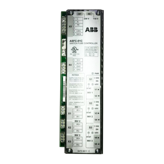
ASFC LEDs
Name
Colour
INV1 STAT
Yellow
INV2 STAT
Yellow
INV3 STAT
Yellow
INV1 UDC
Green
INV2 UDC
Green
INV3 UDC
Green
PWR
Green
Hardware description
Indication
Charging of inverter 1 is
in progress, or Inverter 1
is not in use
Charging of inverter 2 is
in progress, or Inverter 2
is not in use
Charging of inverter 3 is
in progress, or Inverter 3
is not in use
Inverter 1 ready to start
Inverter 2 ready to start
Inverter 3 ready to start
ASFC power on
Illuminates when
Charging monitoring of Inverter 1 is enabled (switch S1 = EN)
and charging current is above 0.7 A.
Switch fuse main contacts are open (auxiliary contact
connected to connector X4 is open).
Charging monitoring of Inverter 1 is disabled (switch S1 = DIS).
See INV1 STAT.
See INV1 STAT.
Signal UDC1 indicates that DC voltage of Inverter 1 capacitor
bank is above 80% of the nominal and charging monitoring of
Inverter 1 is enabled (switch S1 = EN)
See UDC1.
See UDC1.
Voltage for internal logic (5 V) is present (switch fuse handle is
in on position).
