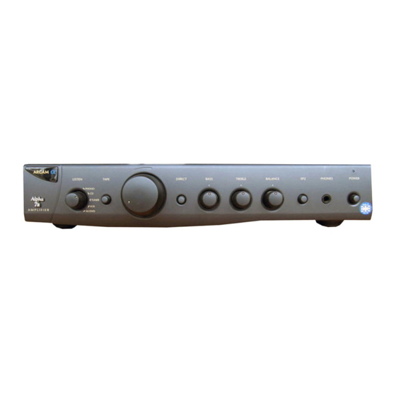
Arcam ALPHA ONE Manual de servicio
Navegue en línea o descargue pdf Manual de servicio para Amplificador Arcam ALPHA ONE. Arcam ALPHA ONE 16 páginas. Arcam cd player handbook
También para Arcam ALPHA ONE: Manual (6 páginas), Manual (6 páginas)

ALPHA ONE/7R/8R/8P AMPLIFIER SERVICE MANUAL
H
/
Arcam Alpha One/ 7R/ 8R/ 8P Amplifier Service Manual
Issue 1 Serial Number 001 - (Paul Newton/ Haider Bahrani Sept '98)
Circuit Description
The Alpha One / 7R/8R and 8P share a common
pcb. The circuits are very similar and the main
differences are the remote volume facility and extra
power output on the 7R and 8R and a switch to
bypass the phono stage to enable its use as an extra
line level input and the AV processor switch on the
Alpha 8R
integrated amplifier. The 8P power
amplifier utilises the same power amplifier circuit as
the Alpha 8R integrated amplifier.
Power Supplies
The ac output of the toroidal mains transformer is
rectified and smoothed by D201-204 and C204, 205.
This is then regulated to +/-15V by Z201, 202 to
power the phono and tone control stages and the
d.c. servo.
The Alpha 7R and 8R transformers have an extra
tapping which is used for the remote volume circuit.
The ac in is regulated to 5V by zener D902 and
associated components and this is then used to
power the microcontroller Z901 and remote receiver.
Phono Stage (Not applicable to Alpha One)
The phono stage consists of a dual opamp Z305, one
opamp per channel.
achieved by the feedback components R703, 704,
702 and C704, 705, 702 on left channel (R603 etc.
as above for Right channel). R703 determines the
gain and C703 the low frequency roll off.
On the Alpha 8R this stage can be bypassed by use
of switch SW302 to enable use as an extra line input.
Tone Controls
The tone control stage is based around Z304 a dual
op amp.
The range of the controls is set by R507, 508 for the
bass pot RV302 and R509, 510 for the treble pot
RV303.
The tone controls and balance pot can be bypassed
by use of the direct switch, SW304.
Power Amplifier
The input to the power amplifier from previous stages
is fed to the differential input of Q112 and Q113.
Q110 and Q111 form a constant current
P
P
S
The RIAA equalization is
E MAN
source for the differential input stage.
The output devices are 'n' channel mosfets SMF045.
Zener diodes D103,104 limit the voltage swing within
safe limits for the output devices & fusible resistors
R105, 106 provide overcurrent damage to the
devices.
A proportion of the output current appears across the
protection network R41,42. If this becomes too high
Q17 is turned on and mutes the output. High D.C.
levels at the output will also mute the output. There
are no output fuses on the Alpha One, 7R and
8R/8P amplifiers. The muting is done by the mute ic
Z303 and its associated compontents. The mute
operates on switch on/off and if an over current or
over voltage condition occurs. The power led glows
amber when the mute circuit is operative and glows
green in normal use.
Removing the Alpha One/ 7R/ 8R/ 8P Transformer
The toroidal transformer is extremely well secured to
the main pcb with a double sided adhesive gasket.
To remove the transformer you must break this
adhesive bond by cutting through the gasket. This
will be easier if the transformer is warm.
Use a cheese wire under the transformer, pulling
backwards and forwards under tension to gradually
cut through. Once most of the adhesive is cut, you
should be able to pull the transformer away from the
pcb.
A less satisfactory substitute for cheese wire is to use
some 22 gauge tinned copper wire, stretched first to
remove kinks, and two temporary handles.
Alpha One/7R/ 8R/ 8P Quiescent Current (IQ)
Settings
When replacing the output transistors of the above
amplifiers it is important to reset the quiescent
current (IQ) to the correct value to prevent the
amplifier blowing again.
The IQ should be checked and set by following the
procedure below:
From cold and with no load or signal connected
Turn both IQ presets (RV1 and RV101) down to
minimum (fully anticlockwise) and set the voltage
drop across resistor R1 (R101 for right hand channel)
to between 3.0 and 3.5mV for the Alpha One and 7R
1
