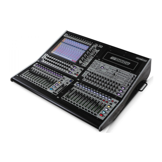
digico SD8 Instrucciones de seguridad y manual de instalación - Página 12
Navegue en línea o descargue pdf Instrucciones de seguridad y manual de instalación para Mezclador de música digico SD8. digico SD8 13 páginas. Replacing and cleaning faders
También para digico SD8: Manual (9 páginas)

Setup & Installation Manual
I/O Rack Audio Connections ........................................................
The number and type of Rack Modules in each type of rack varies according to requirements. See Standard Configuration details
elsewhere.
Function Connector Comments
Analogue Line Inputs 8 x XLR female 8 Channels per card, electronic balanced, Pin 2 Hot
Analogue Mic Inputs 8 x XLR female 8 Channels per card, electronic balanced, Pin 2 Hot
These modules look identical except for Mic or Line ID label on the panel.
Analogue Line Output 8 x XLR male 8 channels per card, electronic balanced, Pin 2 Hot
NOTE: Analogue cards are either input or output and these must be fitted in the correct side of the rack.
AES/EBU Input / Output* 8x XLR 4 Female (input) + 4 Male (Output) floating balanced
TDIF, ADAT, AVIOM and ETHERSOUND modules are optionally available to special order. The console is also compatible with
Optocore's own audio racks. Contact your dealer or the factory for information.
I/O Rack Units
Optocore® Optical Audio Data System (Optional) ....................
It should be noted that all coax MADI connections remain available for use (with the 100m cable length limitation) and can be
considered a backup to the optical system, if required.
The Optocore® system used in Digico mixers is a high speed digital audio data system that allows multiple interface racks to be
connected "daisy chain" along a single optical system.
The HMA battlefield cable and connectors system is a dual in/out (2 lens) bayonet style connector. 2 multichannel audio signals, 1
input 1 output, are carried on each single plug, so there is only 1 connection required per rack. The system actually carries many
more than the single rack capacity of 56 channels in and out. By using an "address" setting on each rack equipped with optical
connectors, 1 optical signal can be sent to several racks, with each rack taking and sending signals independently. All units on the
Mixer system have 2 bi-directional connectors, allowing the optical cable to come from the mixer to the first rack, then out to the
second and so on.
All optical connections should be made with one device's Optocore A Port always connected to the next device's Optocore B Port
throughout the system.
Redundant Optical Operation (Optional) ....................................
A key feature of this system is that, optionally, the Optocore interface provides the ability to have a dual redundant optical path, so
that the system will continue to operate unaffected in the event of a complete cable or connector break. This system combined
with HMA ensure the utmost reliability, even in the event of a cable being destroyed.
The final rack in the daisy chain can be connected back to the mixer with an extra (optionally supplied) cable. This forms a
complete "ring" of data flowing in both directions. In the event of a cable break, the data will continue to flow on the remaining part
of the ring without interruption.
Adjusting Settings in a Multiple Rack System ...........................
The madi interface on the Rack has a "menu" type programming and setting system using 2 pairs of up/down buttons, page and
data, and an LED display.
The Menu is a series of "pages". Use the page ^ and v keys to navigate the pages. This is fully documented in a separate Technical
Note.
DO NOT be tempted to change ANY other setting without good reason and then only after studying the detailed notes. It is
possible to make the rack unusable in a normal system by accident!
The display will show the page item and the data associated with it. The data ^ and v keys are used to
change the displayed setting, where this is possible.
The default display is the primary system status and active sync input. Typically this will read OK:RxA
The LED readout will default to the primary status display, from any previous setting and the buttons will go to a "locked" mode,
where the buttons are disabled, to prevent tampering.
Pressing any button in this state causes dDEC/INC to display.
This is a prompt to unlock (data - Decrement + Increment)
Press both data ^ and v buttons together to release the menu system.
Next press the page up (or down as required) button to show: OptID=30 (or some other number) this sets the Optocore ID. Use
the data up or down button to set the correct number.
The stage rack 1 is normally set for ID=30, stage rack 2 (used on dual rack systems) is normally set for ID=32. Note Mixer is
normally set to ID=0 (set in the mixer software), do not use this in a rack.
Care of the optical cable system .................................................
Whilst the system is very robust, like all connector systems it should be treated with care, the show depends on it!
The HMA connector is a precision machined device containing 2 lenses and an 1/2 turn bayonet style screw locking device.
Because it is an in/out connection, a plug will fit into a socket in 1 direction only.
All connectors have captive dust covers. These MUST be fitted to the exposed connector any time the connector is not in use.
This is to prevent dust landing on the lenses and to give mechanical protection to these expensive devices.
The cable is 2 separate "light pipes" in 1 very strong lightweight outer jacket. The armour just inside the surface of the jacket itself
is nearly impossible to cut by hand with any sort of blade or pull apart except with the aid of machines. However the glass
strands inside can be broken by hard hits or tight bending (like any type of glass!).
Page 12
