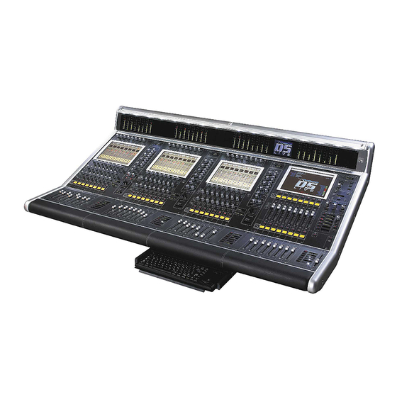
digico D5 Live Manual de inicio rápido - Página 11
Navegue en línea o descargue pdf Manual de inicio rápido para Mezclador digico D5 Live. digico D5 Live 18 páginas. Digital console

Connecting Optocore® Redundant Optical Audio Data System......................................................
For basic connections to the optical cables between the mixer and 1 or 2 racks, refer to the Quick Start
section.
It should be noted that all coax MADI connections remain available for use (with the 50m / 160' cable
length limitation) and can be considered a backup to the optical system, if required.
The Optocore® system used in Digico mixers is a high speed digital audio data system that allows multiple
interface racks to be connected "daisy chain" along a single optical system.
The Stratos HMA battlefield cable and connectors system is a dual in/out (2 lens) bayonet style connector.
2 multichannel audio signals, 1 input 1 output, are carried on each single plug, so there is only 1 connec-
tion required per rack. The system actually carries many more than the single rack capacity of 56 channels
in and out. By using an "address" setting on each rack equipped with optical connectors, 1 optical signal
can be sent to several racks, with each rack taking and sending signals independently. All units on the
Mixer system have 2 bi-directional connectors, allowing the optical cable to come from the mixer to the
first rack, then out to the second and so on. All optical connectors are interchangeable, therefore the order
of cables and connectors in use does not matter. The system will always work.
Redundent
Optical Operation............................................................................................................
A key feature of this system is that, optionally, the Optocore interface provides the ability to have a dual
redundant optical path, so that the system will continue to operate unaffected in the event of a complete
cable or connector break. This system combined with Stratos HMA ensure the utmost reliability, even in
the event of a cable being destroyed. (This option is to be implemented in 1st quarter 2003)
The final rack in the daisy chain can be connected back to the mixer with an extra (optionally supplied)
cable. This forms a complete "ring" of data flowing in both directions. In the event of a cable break, the
data will continue to flow on the remaining part of the ring without interruption.
Adjusting Settings in a Multiple Rack System..............................................................................
The madi interface on the Rack has a "menu" type programming and setting system using 2 pairs of up/
down buttons, page and data, and an LED display.
The Menu is a series of "pages". Use the page ^ and v keys to navigate the pages. This is fully docu-
mented in a separate Technical Note.
DO NOT be tempted to change ANY other setting without good reason and then only after studying the
detailed notes. It is possible to make the rack unusable in a normal system by accident!
The display will show the page item and the data associated with it. The data ^ and v keys are used to
change the displayed setting, where this is possible.
The default display is the primary system status and active sync input. Typically this will read OK:RxA
The LED readout will default to the primary status display, from any previous setting and the buttons will
go to a "locked" mode, where the buttons are disabled, to prevent tampering.
Pressing any button in this state causes dDEC/INC to display.
This is a prompt to unlock (data - Decrement + Increment)
Press both data ^ and v buttons together to release the menu system.
Next press the page up (or down as required) button to show: OptID=30 (or some other number) this sets
the Optocore ID. Use the data up or down button to set the correct number.
The stage rack 1 is normally set for ID=30, stage rack 2 (used on dual rack systems) is normally set for
ID=32. Note Mixer is normally set to ID=20 (set in the mixer software), do not use this in a rack.
Page 11
