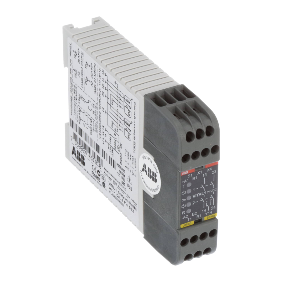
ABB Jocab Safety Vital 3 Manual - Página 6
Navegue en línea o descargue pdf Manual para Controlador ABB Jocab Safety Vital 3. ABB Jocab Safety Vital 3 14 páginas. Safety controller
También para ABB Jocab Safety Vital 3: Instrucciones de uso (11 páginas)

Three connection alternatives
According to PL e (EN ISO 13849-1), connection of sen-
sors/adaptor units in the Vital safety circuit must be made
as the connection examples.
Example
Use separate connection cables from each sensor/adap-
tor unit to the Vital safety controller. Interconnections to be
made via suitable terminals in the control cabinet.
Example
Use Tina4A/Tina8A connector blocks to simplify the con-
nection of externally mounted sensors/adaptor units. Only
Tina4A/Tina8A connector blocks may be used. Use of any
other connector blocks will not meet the safety circuit
requirements.
Example
Use M12-3A and M12-3B 'Y' connectors to connect sen-
sors in series/parallel.
Cable lengths and number of sensor/adap-
tor units for the three connection examples.
In order to determine the number of sensor/adaptor units
that can be connected to a Vital 1 unit it must be remem-
bered that 1 (one) Spot T/R is equivalent to 5 (five) Eden
or Tina units. Units in parallel are equal to one unit. The
following examples provide guidance as to possible con-
figurations and cable lengths using suitable cables.
Example
Up to 1000 metres (0.75 mm
total can be connected to the sensors/units in this example.
The connection is equivalent to 9 Eden or Tina units.
A maximum of 30 Eden or Tina units can be connected to
the Vital 1 unit on a maximum cable length of 500 metres
(0.75 mm
2
conductors) or 300 metres (0.34 mm
Example
Up to 600 metres (0.75 mm
10 metre cables type M12-C1012 (0.34 mm
sor/unit connected to the Tina 8A. This connection example
is equivalent to 17 Eden or Tina units.
ABB
2
or 0.34 mm
2
conductors) in
2
conductors).
2
conductors) to Tina 8A and
2
) to each sen-
A maximum of 3 Tina 8A units, equivalent to 27 Eden/Tina
units (= 3 x 8 connected to Tina 8A + 3 Tina 8A) can be con-
nected to one Vital 1 with a total cable length of 600 metres
(0.75 mm
2)
. Up to 6 Tina 4A units can be connected to one
Vital 1 (equivalent to 30 Eden/Tina units) with a total cable
length of 600 metres (0.75 mm
Example
Either 2 x 500 metre cables (0.75 mm
cabinet and 10 metre cables (0.34 mm
or 2 x 10 metre cables (0.75 mm
and 200 metre cables (0.75 mm
connection is equivalent to 16 Eden or Tina units.
A Total of 30 Eden/Tina units can be connected using a
maximum cable length of 1000 metres (0.75 mm
tres (0.34 mm
2
). If the power supply is only fed from one di-
rection (from one end of the network) the total cable length
is reduced to approx 300 metres (0.75 mm
(0.34 mm
2
).
Connection advice for dynamic sensors to
Pluto and Vital.
Sensors can be connected in many different ways. Here
is some advice that can make connection better and more
stable. The advice is general, but particularly applicable to
the use of Tina 4A and Tina 8A units.
• Never have more than the recommended number of sen-
Never have more than the recommended number of sen-
sors in the loop.
• If possible use a switched mains power supply that can
deliver a stable 24 V DC.
• In the sensor system, use as short cables as possible.
• When connecting a Tina 4A or Tina 8A unit, the supply
voltage at the terminal (out at the unit) must not be less
than 20 Volts.
• Use screened cable, preferably 0.75 mm
from the apparatus enclosure and ground it at one end,
for example at the apparatus enclosure, not at both ends.
• Do not route the signal wiring close to heavy current ca-
Do not route the signal wiring close to heavy current ca-
bling or close to equipment that gives off a lot of interfer-
ence, such as frequency converters for electric motors.
• Never connect "spare" conductors.
• If M12-3B are used for connection of a parallel loop, with
supply to the sensors from two directions, the loop must
be as short as possible. This is because the conduc-
tors that are not being used are also connected, which
increases the capacitive load and reduces the stability of
the system.
2
) to Tina 4A.
2
) from the control
2
) to each sensor/unit
2
) from the control cabinet
2
)to each sensor/unit. The
2
) or 400 me-
2
) and 100 metres
2
or thicker,
1
2
3
4
5
6
7
8
9
10
11
12
13
14
5:11
