Creotech KLMKBM-01 Manual de instrucciones - Página 5
Navegue en línea o descargue pdf Manual de instrucciones para Unidad de control Creotech KLMKBM-01. Creotech KLMKBM-01 17 páginas. Ble mesh

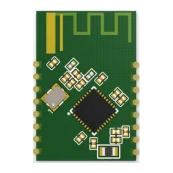
Figure 3.1 Schematic diagram of KLMKBM-01 Bluetooth module
3.2 Pin definition
The interface pin definition is shown in Table 3.2:
Table 3.2 KLMKBM-01 Bluetooth module interface pinout description
No.
Symbol
1
RST
2
ADC
3
PD7
4
PA1
5
B
6
G
7
WW
8
3V3
9
GND
10
PB4
11
SWS
12
PB6
IO
Types
Hardware reset pin (active low), corresponding to
I/O
AI
ADC port, 12bits ADC, corresponding to TL_B1 of the IC
I/O
GPIO port, corresponding to TL_D7 of IC
GPIO port, corresponding to TL_A1 of IC
I/O
GPIO port, can be used as LED drive PWM output, default
I/O
GPIO port, can be used as LED drive PWM output, default
I/O
GPIO port, can be used as LED driver PWM output, default
I/O
P
P
I/O
GPIO port, corresponding to TL_B4 of IC
The programming pin of the module corresponds to TL_D4
I
I/O
GPIO port, corresponding to TL_B6 of IC
Features
RESETB of IC.
corresponding to blue light
corresponding to green light
corresponding to warm white light
Module Power pin (3.3V)
Ground reference
of the IC.
