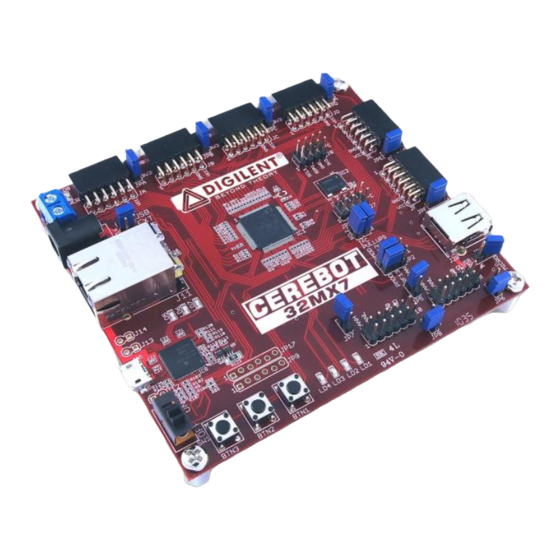
Digilent Cerebot 32MX7 Manual de referencia - Página 8
Navegue en línea o descargue pdf Manual de referencia para Placa base Digilent Cerebot 32MX7. Digilent Cerebot 32MX7 18 páginas.

Cerebot 32MX7 Reference Manual
things as button, switch and LED modules,
connector modules, LCD displays, high current
output drivers, and many others.
There are two styles of Pmod connector: six-
pin and twelve-pin. Both connectors use
standard pin headers with 100mil spaced pins.
The six-pin connectors have the pins in a 1x6
configuration, while the twelve-pin connectors
use a 2x6 configuration. The six-pin
connectors provide four I/O signals, ground
and a switchable power connection. The
twelve-pin connectors provide eight I/O
signals, two power and two ground pins. The
twelve-pin connectors have the signals
arranged so that one twelve-pin connector is
equivalent to two of the six-pin connectors.
The power connection is switchable between
the regulated 3.3V main board supply and the
unregulated input supply.
Digilent Pmod peripheral modules can either
be plugged directly into the connectors on the
Cerebot 32MX7 or attached via cables.
Digilent has a variety of Pmod interconnect
cables available.
See the "Connector and Jumper Block Pinout
Tables" section below for more information
about connecting peripheral modules and other
devices to the Cerebot 32MX7. These tables
indicate the mapping between pins on the
PIC32MX795 microcontroller and the pins on
the various connectors.
User I/O Devices
The Cerebot 32MX7 board provides three push
button switches for user input and four LEDs
for output. The buttons, BTN1 and BTN2 are
connected to I/O pins RG6, RG7 and RD13
respectively. To read the buttons, bits 6 and 7
of PORTG and/or bit 13 of PORTD must be set
as inputs by setting the corresponding bits in
the TRISG and/or TRISD register and then
reading the PORTG and/or PORTD register.
When a button is pressed, the corresponding
bit will be high („1‟).
The four LEDs are connected to bits 12-15 of
PORTG. LED 1 is connected to bit 12, LED 2
www.digilentinc.com
Copyright Digilent, Inc. All rights reserved. Other product and company names mentioned may be trademarks of their respective owners.
is connected to bit 13, and so on. To use the
LEDs, set the desired bits as outputs by
clearing the corresponding bits in the TRISG
register and set the bits to the desired value in
the PORTG register. Setting a bit to 1 will
illuminate the LED and setting the bit to 0 will
turn it off.
CPU Clock Source
The PIC32 microcontroller supports numerous
clock source options for the main processor
operating clock. The Cerebot 32MX7 board is
designed to support either a silicon resonator
from Discera, IC2, for use with the EC
oscillator option, or an external crystal for use
with the XT oscillator option. Standard
production boards will have an 8Mhz Discera
silicon resonator loaded and the EC oscillator
option should be used. If IC2 is not loaded, an
8Mhz crystal will be loaded for X1 (on the
bottom of the board) and the XT oscillator
option should be used. Oscillator options are
selected via the configuration settings specified
using the #pragma config statement. Use
#pragma config POSCMOD=EC
#pragma config POSCMOD=XT
ED option and
to select the XT option.
Using the internal system clock phase-locked
loop (PLL), it is possible to select numerous
multiples or divisions of the 8Mhz oscillator to
produce CPU operating frequencies up to
80Mhz. The operating frequency is selected
via the PIC32MX795 configuration variables.
These are set using the
#pragma config FPLLMUL
statement. Use
set the multiplication factor and
config FPLLDIV
to set the divider for the
internal phased lock loop in the PIC32
microcontroller. Refer to the data sheet for the
PIC32MX7XX family devices for information on
how to choose the correct values, as not all
combination of multiplication and division factor
will work.
to select the
#pragma config
to
#pragma
page 8 of 17
