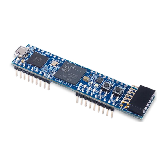
Digilent PLTW S7 Manual de referencia - Página 6
Navegue en línea o descargue pdf Manual de referencia para Placa base Digilent PLTW S7. Digilent PLTW S7 11 páginas.

PLTW S7 Reference Manual
4
Oscillators/Clocks
The PLTW S7 includes a 12 MHz crystal oscillator connected to pin M9 (an MRCC input on bank 14). This clock is
intended to be used as a general-purpose system clock. The clock can drive MMCMs to generate clocks of various
frequencies and with known phase relationships that may be needed throughout a design. The 12 MHz input clock
cannot directly drive a PLL because they have a minimum input frequency of 19 MHz. Some rules restrict which
MMCMs and PLLs may be driven by the 12 MHz input clock. For a full description of these rules and of the
capabilities of the Spartan-7 clocking resources, refer to
User Guide".
Xilinx offers the Clocking Wizard IP core to help users generate the different clocks required for a specific design.
This wizard will properly instantiate the needed MMCMs and PLLs based on the desired frequencies and phase
relationships specified by the user. The wizard will then output an easy-to-use wrapper component around these
clocking resources that can be inserted into the user's design. The clocking wizard can be accessed from within the
Vivado and IP Integrator tools.
5
USB-UART Bridge (Serial Port)
The PLTW S7 includes an FTDI FT2232HQ USB-UART bridge (attached to Micro-USB connector J5) that allows the
user to use PC applications to communicate with the board using standard Windows COM port commands. Free
USB-COM drivers, available from
to UART/serial data. Serial port data is exchanged with the FPGA using a two-wire serial port (TXD/RXD). After the
drivers are installed, I/O commands can be used from the PC directed to the COM port to produce serial data
traffic on the K15 and L12 FPGA pins.
An onboard status LED (LD6) provides visual feedback on traffic flowing through the port.
The FT2232HQ is also used as the controller for the Digilent USB-JTAG circuitry, but the USB-UART and USB-JTAG
functions behave entirely independent of one another. Programmers interested in using the UART functionality of
the FT2232 within their designs do not need to worry about the JTAG circuitry interfering with the UART data
transfers, and vice-versa. The combination of these two features into a single device allows the PLTW S7 to be
programmed, communicated with via UART, and powered from a computer attached with a single Micro USB
cable.
The connections between the FT2232HQ and the Spartan-7 are shown in Figure 5.1. Signal names that imply
direction are from the point-of-view of the DTE (Data Terminal Equipment), in this case, a PC connected to the
Micro USB port.
Copyright Digilent, Inc. All rights reserved.
Other product and company names mentioned may be trademarks of their respective owners.
Xilinx
Figure 4.1. Clock input.
FTDI's website
under the "Virtual Com Port" or VCP heading, convert USB packets
UG472, titled "7 Series FPGAs Clocking Resources
Page 6 of 11
