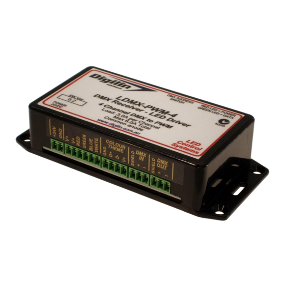
Digilin LDMX-PWM-4 Manual del usuario - Página 4
Navegue en línea o descargue pdf Manual del usuario para Controlador Digilin LDMX-PWM-4. Digilin LDMX-PWM-4 9 páginas. 4 channel dmx led driver

4 C h a n n e l D M X L E D D r iv e r - L D M X - P W M - 4
U s e r M a n u a l
5 .2 - 4 N o v e m b e r 2 0 1 6
Using With Colour Theme Input
In order to connect a Colour Theme Controller the DMX address should be set to 1 and the Input
Select Switch (switch 10 of the DMX address switch, as shown in Figure 1) should be in the up
position. When data is being correctly received, the green LED should be on. It is possible to connect
further DMX receivers to this unit. They should be configured to operate with a standard DMX input
(not a Colour Theme Input) with the DMX address set to 1.
Using With DMX Input
In order to use the LDMX-PWM-4 with a DMX feed simply set the desired address and connect the
DMX feed to the DMX input. Remember to terminate the DMX feed at the end of the chain with a
120Ω resistor between the DMX + & - lines. When data is being correctly received, the green LED
should be on.
Test Mode
The LDMX-PWM-4 has a test mode which ramps each individual output up to full brightness then
back off in sequence. This test mode is entered by setting the DMX address to 0 (all switches down).
While in this mode, any incoming DMX data is ignored. Once the address is changed from 0, the unit
will complete the current cycle of the test, then return to normal operation.
Fallback Output
By default, the LDMX-PWM-4 outputs will be set at 50% for all channels at start-up and loss of DMX
signal.
P a g e 4 o f 9
