Cisco Catalyst 3550 Manual de introducción - Página 13
Navegue en línea o descargue pdf Manual de introducción para Interruptor Cisco Catalyst 3550. Cisco Catalyst 3550 33 páginas. Cisco catalyst 3550: supplementary guide
También para Cisco Catalyst 3550: Boletín de productos (3 páginas), Boletín de productos (5 páginas), Ficha de datos (21 páginas)
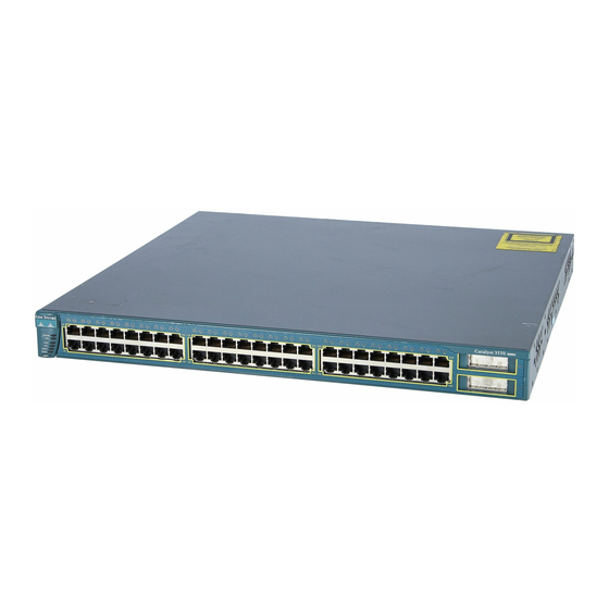
Attaching the Brackets
Use six Phillips flat-head screws to attach the long side of the brackets on the Catalyst 3550-24 and
3550-48 switches.
1
2
3
4
5
6
1X
7
SYS TEM
8
9
10
RPS
STA TUS
UTI L
DU PLX
SPE ED
MO DE
2X
1
2
3
4
5
6
1X
7
SYS TEM
8
9
10
11
RPS
12
13
14
15
STA TUS
UTI L
DU PLX
SPE ED
MO DE
2X
10 0- 24
0V ~
5- 3A
50 /6 0H
z
11
12
13
14
15
16
17
18
19
20
21
22
15X
17X
23
24
25
26
27
28
29
30
31
32
33
34
31X
33X
16X
18X
32X
34X
Front-mounting position
16
17
18
19
20
21
22
15X
17X
23
24
25
26
27
28
29
30
31
32
33
34
35
36
37
38
31X
33X
39
40
16X
18X
32X
34X
Mid-mounting position (telco rack)
DC OU
TP UT
1
Rear-mounting position
35
36
37
38
39
40
41
42
43
44
C at al y st
45
46
47
3 5 5 0
48
47X
1
48X
2
41
42
43
44
C at al y st
45
46
47
3 5 5 0
48
47X
1
48X
2
C O N SO
LE
Number-8 Phillips
flat-head screws
13