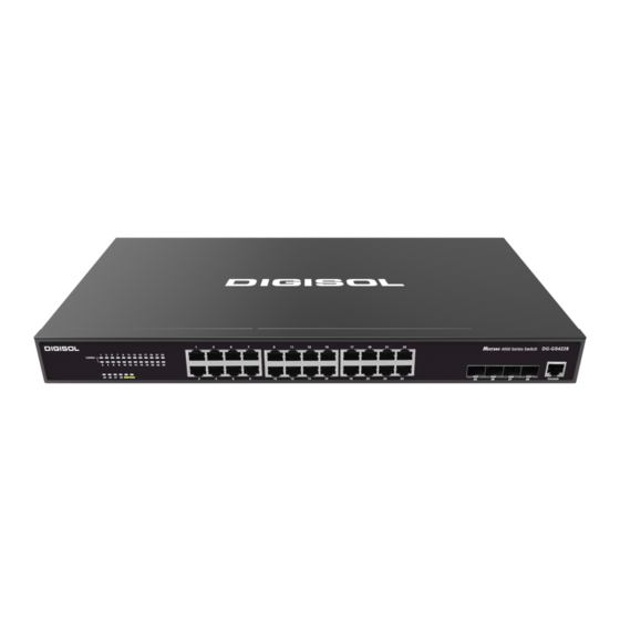
Digisol DG-GS4628HPE-P Manual de instalación - Página 17
Navegue en línea o descargue pdf Manual de instalación para Interruptor Digisol DG-GS4628HPE-P. Digisol DG-GS4628HPE-P 19 páginas. Giga layer 2 switches

Step 2: Attach one end of the fiber cable to the SFP/XFP transceiver, and attach the
other end to the transceiver of the corresponding devices. Note: The SFP/XFP
transceiver's TX port should be connected to the RX port of the corresponding
device, and vice versa.
Step 3: Check the fiber port status indicator, a lighted LED indicates that the link has
been established; otherwise the link is not ready and should be examined.
Caution!
Please verify the sign above the port to ensure using the other ports. Connecting to
wrong ports might damage the transceiver or the other ports. When connecting other
devices through a fiber cable to the switch, the output power of the fiber cable must not
exceed the maximum received power of the corresponding modules. Otherwise, it will
damage the fiber transceiver. Do not stare at the fiber bore when the switch is in operation.
That may hurt your eyes.
2.3.5 Power Supply Connection
DG-GS4200 series use the power is 220VAC. Please read the power input
specification for the detailed information.
Power supply connection procedure is described as below:
1. Insert one end of the power cable provided in the accessory kit into the power source
socket (with overload and leakage protection), and the other end to the power socket in
the back panel of the switch.
2. Check the power status indicator in the front panel of the switch. The corresponding
power indicator should light. DG-GS4200 series is self-adjustable for the input voltage. As
soon as the input voltage is in the range printed on the switch surface, the switch can
operate correctly.
3. When the switch is powered on, it executes self-test procedure and startups.
Fig 2-4 Connecting power to switch
2-9
DG-GS4200 Installation Guide
