Digital Acoustics IP7-FX Manual de introducción - Página 2
Navegue en línea o descargue pdf Manual de introducción para Unidad de control Digital Acoustics IP7-FX. Digital Acoustics IP7-FX 4 páginas. Talkmaster
También para Digital Acoustics IP7-FX: Manual de introducción (4 páginas)
New Installations
The IP7-FX can be mounted indoors or outdoors in a weather tight enclosure.
•
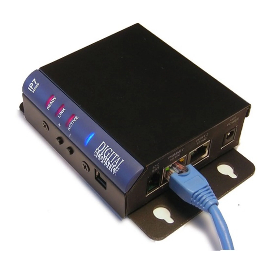
If PoE (Power over Ethernet) is not
available, connect the IP7-FX's
Ethernet port to a network switch
using a standard RJ-45 cable.
Connect the IP7-FX to an external
12VDC (1.2 Amps) or 24VDC (2.5
Amps) power supply using either J1-
1 (+) and J1-2 (-) terminals or a
2.5mm barrel connector (center tip
positive)
•
If PoE is available, connect the IP7-
FX's Ethernet port to a PoE (802.3af) network switch or injector using a standard RJ-45 network cable. It
will request 15.4 watts from the power source equipment.
•
The Link LED will turn solid. The Ready LED will begin flashing 4x per second
•
The IP7-FX can use either a mic level or line level microphone. Connect a mic level microphone to the
J2-1 (Mic+) and J2-2 (Mic-) terminals. Optionally, connect a line level microphone using J3-4 (Line In),
J3-6 (Ground) and J3-7 (Mic Power – 12V). Use 20-22 AWG twisted, shielded wire. The Microphone wire
cannot be in the same jacket as the speaker wire. The internal ST-MIC switch (located on the DIN clip
side) must be in the MIC position
•
The IP7-FX can also use the speaker (connected to the J2-6 and J2-7 connectors) as a microphone (half
duplex mode only). To enable this mode, slide the internal ST-MIC switch (located on the DIN clip side) to
the ST position
•
The IP7-FX can drive either an 8 Ohm speaker or an amplifier. Connect an 8 Ohm speaker to the J2-6 and
J2-7 (polarity independent) terminals using 18 AWG. To connect to an amplifier or self-amplified speaker,
connect the J2-3 (Line Out) to the amplifier's "+" terminal and J2-4 (ground) to its "-" terminal using 18 – 22
AWG. Follow any recommendations by the amplifier's manufacture for balanced vs unbalanced audio
signals.
•
The IP7-FX can initiate a SIP call by grounding the J2-5 (Talk) connector. Connect a button or switch to
J2-5 (Talk) and J2-4 (Ground) using 18 – 22 AWG wire. When J2-5 is grounded, the IP7-FX will dial a
number stored in the IP7-FX configuration
•
If the relay will be used to activate an electronic door strike, connect the J3-2 (COM) and either the J3-1
(NO) or J3-3 (NC) to the door strike. The relay can be activated during a call by entering a code on a
telephone keypad that is stored in the IP7-FX configuration
•
The IP7-FX can be DIN rail or surface mounted. To install on a standard 35mm DIN rail using the
integrated DIN clip, tilt the top of the unit (J1, J2, J3 connectors facing up with Volume buttons facing
forward) back towards the DIN Rail until the IP7 DIN clip catches the top of the rail. Press in at the bottom
of the IP7 to snap into place). To surface mount, snap the included Mounting Plate in half, line the two
pieces (beveled holes facing up) with the screw holes on the bottom of the IP7-FX case and secure it using
the provided screws so that the mounting holes extend past the J1, J2 and J3 edge of the case
•
Record the ID# from the label on back of the IP7-FX for use during software configuration.
•
Optionally, the extra ID# label can be used for easy identification of this location
•
Please refer to the IP7-FX_ReferenceManual available at https://www.digitalacoustics.com/support/ip7-
hardware-talkmaster-software-manuals/ for additional information on installation
Page 2 of 4
Digital Acoustics IP7-FX
Installation and SIP Configuration