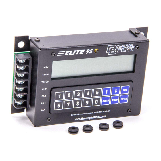
DIGITAL DELAY Elite 95 Manual - Página 3
Navegue en línea o descargue pdf Manual para Unidad de control DIGITAL DELAY Elite 95. DIGITAL DELAY Elite 95 11 páginas.

Features:
• Microprocessor controlled timing
• Discrete I/O (input - output) construction
• Retains all numbers even with power disconnected from unit
• Large illuminated display for easy reading of information day or night
• Self-test mode on all display functions
• Dust & splash-proof backlit keypad with detent (positive feel)
• Hit the tree twice with one or two separate button
• Instant timing cycle reset
• Programmable Push-button Interrupt Time
• Programmable Tap Up and Down feature for the delay (In Push-button Mode 1, 3, or 4)
• Programmable Starting Line Enhancer
• Built-in Driver's Reaction Tester with LED
Specifications:
• Input Voltage Range: 10 to 18 Volts DC (16 Volt compatible)
• Operating Temperature Range: 0 to 150 degrees F.
• Push-button Current: .1 AMPS at 12 VDC
• Three Separate Inputs
• PB 1
• PB 2 or Tap Up PB
• Tap PB
+12VDC Terminal:
driving all outputs at the same time.
Transbrake Terminal:
connects to the low side of the 2-Step, if used.
Throttle Stop Terminal:
can then be used as a Starting Line Enhancer or down track Throttle Stop.
Ground Terminal:
aluminum.
PB-1 Terminal:
In Push-button Modes 1 and 2 the Push-button connected to PB 1 terminal is used to control the
primary delay only. In Push-button Modes 3 and 4 the Push-button connected to PB 1 terminal is used to control the primary
delay and the secondary delay in sequence.
PB-2 Terminal:
In Push-button Mode 2 the Push-button connected to PB 2 terminal is used to control the secondary
delay only. In Push-button Modes 1, 3, or 4 the Push-button connected to this terminal can be used as a Tap Up Push-button.
Tap Terminal:
In Push-button Mode 2 the Push-button connected the Tap terminal can be used as either a Tap Up or Tap
Down. When in Push-button Modes 1, 3, or 4 the Push-button connected to the Tap terminal can only be used as a Tap Down.
Features and Specifications
The Terminal Strip
Connect the +12VDC terminal to a switched +12 Volt source with enough amperage capable of
Connect the Transbrake terminal to the Transbrake solenoid. The Transbrake terminal also
Connect the Throttle Stop terminal to the Throttle Stop solenoid, if used. The Throttle Stop
Connect the Ground terminal to the Neg. terminal on the battery or to good steel ground, not
3
