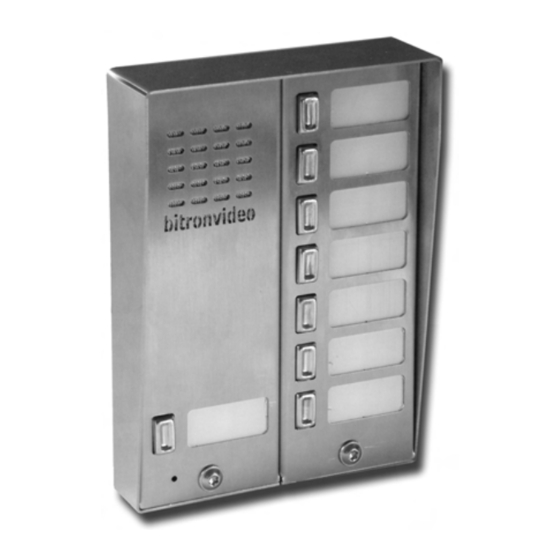
Bitron Video AV1183 Series Manual de instrucciones - Página 8
Navegue en línea o descargue pdf Manual de instrucciones para Sistema de interfono Bitron Video AV1183 Series. Bitron Video AV1183 Series 8 páginas. 1+n m-inox push button panel

The dimensions of the reading window are 31 x 14 mm with 18 mm gap in between (Fig. 5).
To insert the printed name card, remove the entire block (Fig. 3) formed by a white plastic element and a
transparent Plexiglas element, remove the protective fi lm from the latter, dispose of the white plastic element
and position the printed name card behind the Plexiglas element, inserting it in its seat. Make sure the names
are correctly centred in the reading window.
Close the module making sure that the slots on the upper part of the lid are inserted on the protrusion on the top
of the module, push upwards, lower the lid and fasten the specifi c screw with the tool provided (Fig. 6 - 7).
Remember to check that the microphone hole on the bottom left is aligned with the hole on the module
lid.
CONNECTION TERMINALS
CH
= Doorphone sensor and call
AP
= Electrical lock terminal (closed to ground)
D
= Floor call
CP
= Button common (doorphone call)
~
= 12 Vac power from transformer
0
= Power negative from transformer and system ground (to doorphones)
CD
= Diode common to other rows or to relay box for special applications
X
= CD from relay box for one or more on-board buttons (after cutting sealed CD jumper)
The correct connection of the two wires to the "0" terminal is crucial to prevent buzzing.
CONNECTIONS
The following rules must be observed for connections:
−
Respect the instructions shown in the table (Fig. 8) carefully.
−
Avoid installing system wires close to electrical mains wires (they should be at least 30 cm apart).
−
Connect the ground wires exactly as shown in Fig. 9 to avoid buzzing.
Position the transformer at a maximum distance from the door panel of 20 metres.
2
Use 1 mm
wires for connecting terminals ~ and 0. Also respect the connections shown on the diagram
to prevent noise.
VOLUME ADJUSTMENT
The entrance panel audio unit settings are optimal for a system of average size by default.
The settings may however need to be changed.
Proceed as follows in such a case (Fig. 10)
−
External volume: turn trimmer EXT clockwise to turn the volume up and anticlockwise to turn it down.
−
Internal volume: turn trimmer INT in a similar way.
Turn down both volumes slightly if feedback loop howl occurs to eliminate the problem.
CALL CONFIRMATION EXCLUSION
The entrance panel generates a confi rmation tone when the doorphone call is sent to the doorphone. This tone
may be deactivated by cutting the "RC" jumper near the entrance unit terminal board as shown in (Fig. 11).
8
ELECTRONIC DOORPHONE OR BUZZER CALL SELECTION
CALL TYPE (E R)
This jumper is used to select the doorphone call type made by the audio unit when the button is pressed on
the unit or panel.
There are two possible modes (Fig. 12).
−
ELECTRONIC (Default): When the jumper is positioned on the central pin and E (electronic).
A tone suited to all new-generation doorphones will be generated in this confi guration.
−
BUZZER when the jumper is positioned between central and R (buzzer).
In this confi guration, the unit will generate a tone adapted to all old model doorphones supporting
mechanical buzzer calls. A 100Hz tone will be generated.
CALL SHORT CIRCUIT PROTECTION
The protection system will cut off calls for a few seconds in the event of a calling terminal short circuit. After
this time, the entrance panel will be able to generate a new call. The cycle will be repeated if the short circuit
persists.
BUTTON COMMON (CP) AND DIODE COMMON (CD) CONNECTION
The buttons on the audio module are already connected to the button common and the diode common by
means of two jumpers (CP and CD) selectable for special applications. Consequently, connect the users to
terminals C1 user 1 and C2 user 2 for 1-2 button audio modules AV1183/001 - AV1183/002.
When using a 2 or 3 row PE, use a piece of wire to connect CP on the audio section (on the right of the module)
(Fig. 9a) to CP of the adjacent button module on the bottom right and use another piece of wire to connect
CD on the audio section terminal board to CD on the key module terminal board next to the CP terminal. Use
the button terminals from C1 to C7 for audio and doorphone calls to each user: be careful not to connect the
users on the right of the CP part because calls on the doorphones connected to the terminal will always be
active.
012175604.10
012175604.10
9
