Siemens 3AF 01 Manual de instrucciones - Página 13
Navegue en línea o descargue pdf Manual de instrucciones para Equipamiento industrial Siemens 3AF 01. Siemens 3AF 01 24 páginas. Outdoor vacuum switchgear

(3)
Any locking washer or gasket loosened or
exposed during assembly must be replaced.
The following sequence should be followed :
(i)
In line with the foundation plan shown in the
G.A. drg., the foundation pockets are made.
Grout the foundation bolts and cure. Ensure the
foundation area is leveled for proper seating of
the circuit-breaker.
(ii)
Mount the support structure on to the grouted
bolts, fully tighten the foundation bolt
hardware.
(iii)
The pull rod length is factory preset. Do not
change it.
(iv)
The contacts of the vacuum interrupter are in
the open position during transport.
(v)
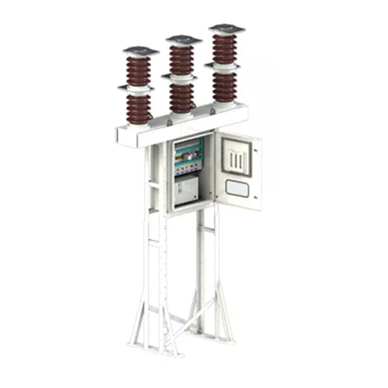
Place the breaker assembly (P-2, Fig. 7) over the
support structure and fix the assembly with the
hardware supplied
(M12 x 50 Bolt). Take care to strictly follow the
lifting instructions, with special care of porcelain
insulators.
6.5
Electrical connections
(i)
Earthing
Connect the vacuum circuit-breaker to the
appropriate high-voltage protective earth by
means of the suitably marked earth terminals on
the base frame using flat copper, copper cable
or hot galvanized steel strip.
(ii)
Drill suitable holes on the gland plate. Run the
control cables into the mechanism housing
through the cable glands which will be mounted
on the gland plate (K; Fig. 1). Connect the
protective conductors to the earthing terminals
provided. Connect the auxiliary supply as per
the approved schematic/wiring diagram.
CAUTION
When the supply voltage is applied, the motor
immediately charges the closing spring.
(iii)
Cleaning
WARNING
For safety reasons, cleaning may be taken up only
when the vacuum circuit-breaker is in the open state,
closing spring discharged.
Non-observance can result in personal injury.
Use only warm water with a mild liquid household
detergent added as cleaning agent.
(iv)
Using 5kV kit, megger the system to confirm
insulation resistance of min. 100 M ohms.
(v)
Terminal connectors and/or Flat bar
connections:
Prior to fitting the conductors, position them to ensure
that they have smooth contact with their connecting
parts and are fully aligned with the holes of terminal
pads.
Rub the contact faces to be bolted together with
crisscrossing strokes using a wire brush or emery cloth (for
metal grain size 150) until bright metal shows, and then
wipe with a clean rag. Thinly grease the bright contact
faces with acid-free Vaseline (e.g. Shell Vaseline 8420)
and bolt them together immediately.
Differing contact materials (AI/Cu) must not be worked
with the same cleaning tool.
Use the M12 nuts and bolts of strength class 8 and
corresponding spring elements and plain washers.
Use cupal sheets while mounting copper terminal
overhead connectors to avoid galvanic corrosion with a
aluminium alloy top and bottom flanges.
11
