Siemens 3VT9.00-1CB.2 Manual - Página 3
Navegue en línea o descargue pdf Manual para Equipamiento industrial Siemens 3VT9.00-1CB.2. Siemens 3VT9.00-1CB.2 12 páginas. Accessory for molded-case circuit-breakers

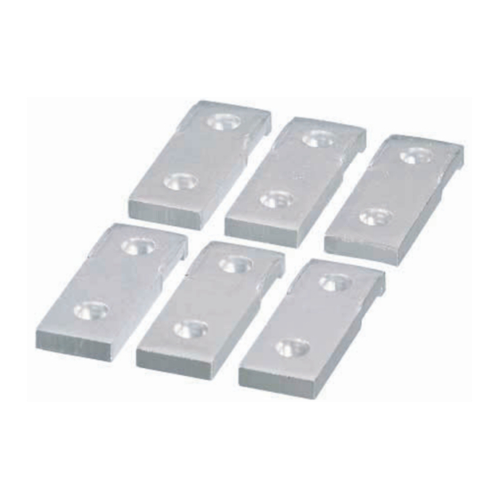
Accessory for 3VT circuit-breakers — Extended front connecting bars
Safety Instructions
Read and understand these instructions before installing,
operating, or maintaining the equipment.
DANGER
!
Hazardous voltage.
Will cause death or serious injury.
Disconnect power before working on equipment.
CAUTION
Reliable functioning of the equipment is only ensured with
certified components.
Installation procedures for VT63, VT100, VT160 extended front
connecting bars
(1) VT63, VT100, VT160 extended front connecting bars
(2) Step 1: Insert and attach the extended front connecting bars
on the load and line sides of the circuit-breaker.
(3) Circuit-breaker assembled with extended front connecting
bars
Installation procedures for VT250, VT400 extended front
connecting bars
(4) VT250, VT400 extended front connecting bars
(5) Step 1: Insert and attach the extended front connecting bars
on the load and line sides of the circuit-breaker.
(6) Circuit-breaker assembled with extended front connecting
bars
Installation procedures for VT630 extended front connecting
bars
(7) Step 1: Insert and attach the extended front connecting bars
on the load and line sides of the circuit-breaker.
(8) Circuit-breaker assembled with extended front connecting
bars
Size of extended front connecting bars for 3VT molded case
circuit-breaker
VT63-VT100 busbars
Ampere ratings:
I
10 A ~ 20 A: length X width X thickness X diameter = 27 X 10
n
X 1 X F3
Ampere ratings:
I
25 A ~ 50 A: length X width X thickness X diameter = 31 X 10
n
X 2 X F5
Ampere ratings:
I
63 A ~ 100A: length X (long width/short width) X
n
thickness = 38 X (16 / 10) X 4
VT160 busbars
Ampere ratings:
I
32 A ~ 50 A:
n
length X width X thickness X diameter = 31 X 10 X 2 X F5
Ampere ratings:
I
63 A ~ 160 A: length X (long width / short width) X thick-
n
ness = 38 X (16 / 12) X 4
A5E00817840-01
VT250 busbars
Length X width X thickness = 56 X 20 X 6
VT400 busbars
Length X width X thickness = 56 X 25 X 6
VT630 busbars
Length X width X thickness = 70 X 40 X 6
Main dimension tables for VT250-VT630 installation:
Plug-in type-plate
front connection
I
n
W1
L1
H1
D1
250 A
20
10
5
8.2
400 A
25
14
5
10.2
630 A
—
630 A 40
English
Fixed type-plate front
connection
Extended plate front
I
n
connection
W1
L1
H1
250 A
20
12.5
6
400 A
25
12.5
6
630 A
40
10
5
Withdrawable type-plate
front connection
W1
L1
H1
D1
—
25
14
6
10.2
40
20
10
14
Fixed type-plate front connection
I
n
W1 L1
L2
H1
D1
12
12
10
11
D1
8,5
11
11
D2
6.5
3
