Siemens Simatic S7-300 Manual - Página 24

Navegue en línea o descargue pdf Manual para Equipamiento industrial Siemens Simatic S7-300. Siemens Simatic S7-300 32 páginas. Automation systems, controlling a physical axis
También para Siemens Simatic S7-300: Manual del usuario (34 páginas), Manual (21 páginas), Instrucciones de uso (4 páginas), Instrucciones de uso (5 páginas), Manual (35 páginas), Primeros pasos (8 páginas), Primeros pasos (16 páginas), Descripción de la aplicación (24 páginas), Manual (18 páginas), Manual de instalación y hardware (20 páginas), Primeros pasos (32 páginas)
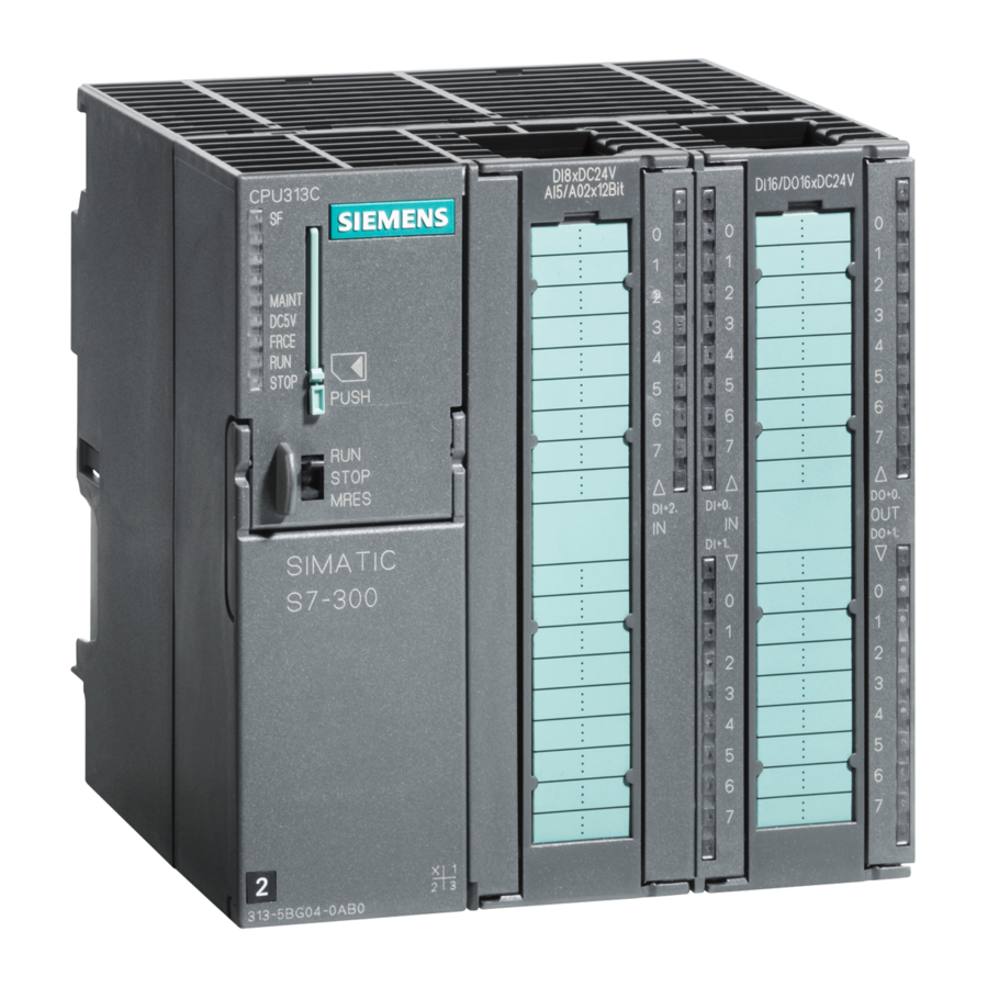
Siemens Simatic S7-300 Manual
Measuring ranges
You perform the setting of the measuring ranges by means of the measuring range
modules on the module and with the "measuring method" parameter in STEP 7.
Table 10
Measuring ranges of the SM 331; AI 8 x 14 Bit High Speed
Method Selected
U: voltage
4DMU: Current (4-wire
transmitter)
2DMU: Current (2-wire
transmitter)
Default Settings
The default settings of the module in STEP 7 are the "voltage" measuring method
and the "" 10 V" measuring range. You can use this measuring method with this
measuring range without parameterizing the SM 331; AI 8
using STEP 7.
Special characteristics of the wire-break check for the 4 to 20 mA measuring
range
With a parameterized measuring range of 4 to 20 mA and enabled wire-break
check, the analog input module enters wire-break in the diagnosis when a current
falls below 3.6 mA.
If you have enabled diagnostics interrupt during configuration, the module
additionally triggers a diagnostic interrupt.
If no diagnostic interrupt has been enabled, the illuminated SF LED is the only
indication of the wire-break and you must evaluate the diagnostic bytes in the user
program.
With a parameterized measuring range of 4 to 20 mA and disabled wire-break
check and enabled diagnostic interrupt, the module triggers a diagnostic interrupt
when the underflow is reached.
24
Measuring Range
(Type of Sensor)
" 1 V
" 5 V
1 to 5 V
" 10 V
0 to 20 mA
4 to 20 mA
" 20 mA
4 to 20 mA
Product Information on the Manual S7-300 Module Specifications, Edition 11/2002
Measuring Range
Module Setting
A
You will find the digitized analog
values in Section 4.3.1 of the
B
reference manual in the part that
deals with the voltage measuring
range.
C
You will find the digitized analog
values in Section 4.3.1 of the
reference manual in the part that
deals with the current measuring
D
range.
Description
14 Bit High Speed
A5E00213444-02