Siemens Simatic S7-300 Manual - Página 28

Navegue en línea o descargue pdf Manual para Equipamiento industrial Siemens Simatic S7-300. Siemens Simatic S7-300 32 páginas. Automation systems, controlling a physical axis
También para Siemens Simatic S7-300: Manual del usuario (34 páginas), Manual (21 páginas), Instrucciones de uso (4 páginas), Instrucciones de uso (5 páginas), Manual (35 páginas), Primeros pasos (8 páginas), Primeros pasos (16 páginas), Descripción de la aplicación (24 páginas), Manual (18 páginas), Manual de instalación y hardware (20 páginas), Primeros pasos (32 páginas)
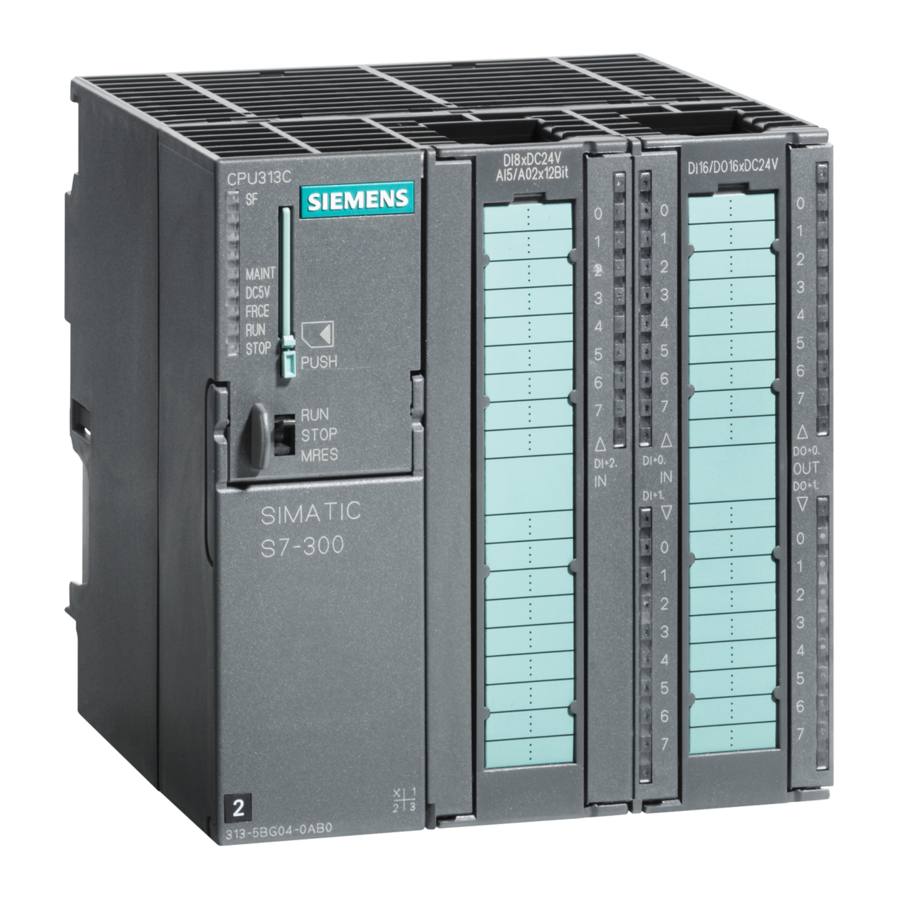
Siemens Simatic S7-300 Manual
Suppression of interference, Limits of Error
Crosstalk between
outputs
Operational limit (in the entire temperature range, with
reference to the output range)
S
Voltage outputs
S
Current outputs
Basic error (operational limit at 25° C, referred to output
range)
S
Voltage outputs
±10 V
0 to 10 V
1 to 5 V
S
Current outputs
±20 m
0 to 20 mA
4 to 20 mA
Temperature error (with
reference to the output range)
S
Voltage outputs
S
Current outputs
Linearity error (with reference to
the output range)
Repeat accuracy (in the steady
state at 25° C, referred to the
output range)
Output ripple; band width 0 to
50 kHz (with reference to the
output range)
Status, Interrupts, Diagnostics
Interrupts
S
Diagnostic Interrupt
Diagnostic functions
S
Group error display
S
Diagnostic information
readable
Substitute value can be applied
28
> 100 dB
±0.12%
±0.18%
±0.02%
±0.02%
±0.04%
±0.02%
±0.02%
±0.04%
± 0.0025% / K
± 0.004% / K
±0.004%
±0.002 %
±0.05 %
Programmable
Programmable
Red LED (SF)
Possible
Yes, programmable
Product Information on the Manual S7-300 Module Specifications, Edition 11/2002
Data for Selecting an Actuator
Output ranges (rated values)
S
Voltage
S
Current
Load resistance (in the nominal
range of the output)
S
For voltage outputs
Capacitive load
S
For current outputs
Inductive load
Voltage outputs
S
Short-circuit protection
S
Short-circuit current
Current outputs
S
No-load voltage
Destruction limit against
voltages/currents applied from
outside
S
Voltage at outputs to M
ANA
S
Current
Connection of actuators
S
For voltage output
Four-conductor
connection (measuring
circuit)
S
For current output
Two-conductor
connection
±10 V
0 to 10 V
1 to 5 V
±20 mA
0 to 20 mA
4 to 20 mA
min. 1 kΩ
max. 1 µF
max. 500 Ω
max. 1 mH
Yes
max. 40 mA
max. 18 V
max. 15 V continuous
75 VDC for max. 0.1 s
(pulse duty factor 1 :
20)
max. 50 mA DC
Possible
Possible
A5E00213444-02