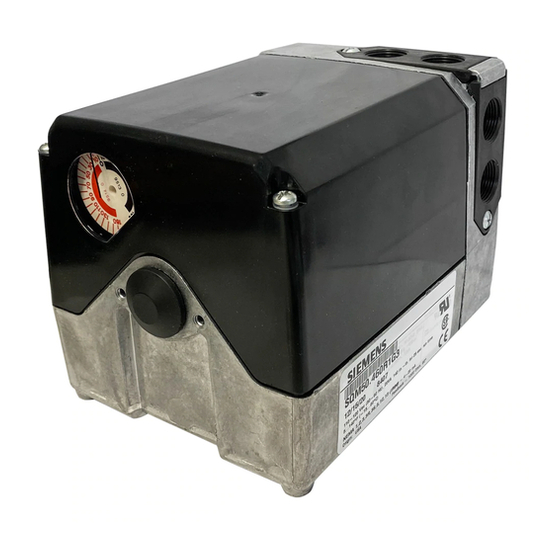
Siemens SQM56.667R1G7R Instrucciones técnicas - Página 24
Navegue en línea o descargue pdf Instrucciones técnicas para Controlador Siemens SQM56.667R1G7R. Siemens SQM56.667R1G7R 31 páginas. Reversing
También para Siemens SQM56.667R1G7R: Instrucciones técnicas (31 páginas), Instrucciones técnicas (31 páginas)

Technical Instructions
Document No. 155-517P25
July 9, 2007
AGA56.9A...
Circuit Board
Installation, Continued
AGA56.1A97
Circuit Board
Installation
Page 24
8. Gently guide the L-shaped circuit
board containing the three blue trim
potentiometers into the vertical support
slots located on the cam drum side of
the actuator. See Figure 27.
9. Slide the circuit board downward until
both supports snap into place. Install
the ASZ... potentiometer. (See
Potentiometer Removal/Installation
Instructions.)
10. Connect the bundled blue, black and
brown potentiometer wires to the
terminal block located on the ASZ...
potentiometer circuit board.
1. Install the AGA56.1A97 circuit board into the two slotted circuit board supports
located on the switch housing side of the actuator.
2. Gently guide the AGA56.1A97 circuit board into the support slots and slide the board
downward until both supports snap into place.
3. Make the following connections to the actuator:
a. Connect the wire, marked "1" from the circuit board to switch I, terminal 1.
b. Connect the wire, marked "2" from the circuit board to switch II, terminal 2.
c. Connect the wire, marked "13" from the circuit board to switch III, terminal 13.
SQM5... Reversing Actuators
18
17
16
15
14
13
12
11
28
27
26
25
24
23
22
21
8
7
6
5
4
3
2
1
VIII
VII
VI
V
IV
III
II
I
N
1
MAN.
0
AUTO
N
Figure 26.
L - SHAPED
CIRCUIT
Figure 27.
Siemens Building Technologies, Inc.
13
3
2
BOARD
