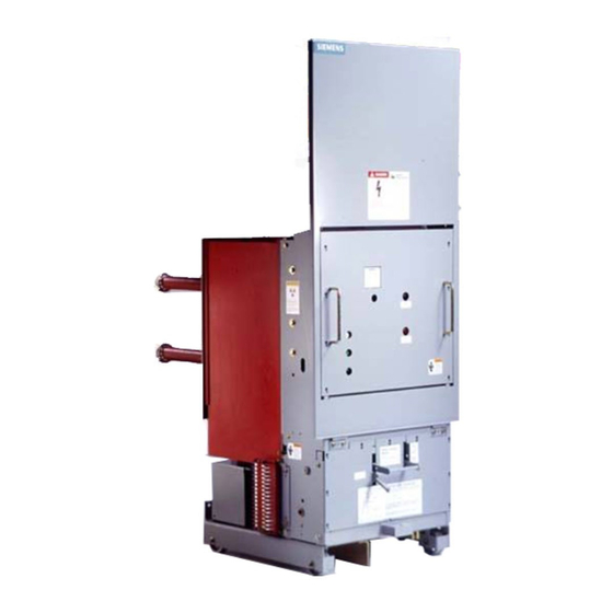
Siemens 15-FSV-750 Instalación Funcionamiento y mantenimiento - Página 43
Navegue en línea o descargue pdf Instalación Funcionamiento y mantenimiento para Interruptor Siemens 15-FSV-750. Siemens 15-FSV-750 48 páginas. Vacuum circuit breakers fsv series and msv series

Vehicle
Description
Continuous Current Interlock
Reference Figure 26
The continuous cu rrent i nterlock functions to ensure breakers
and cubicles of l i ke continuous rating are applied, and that
breakers with dissimilar continuous cu rrent ratings are ex
cluded from cu bicles of u n l ike current ratings
Figure 26 provides detail necessary to determine continuous
cu rrent ratings and appropriate i nterlock orientation.
\
!
Figure 27
Control Cable Connection Detail
1
I I
I
I
/
/ 1
_.- / /
/
+
Side
Control Cable And
Connection Box
The MSV and FSV type circuit b reakers em ploy a plug-1n cable
which completes all standard c 1 rcu1t breaker electrical con
nections between the mechanism housing and the veh icles
secondary d isconnects. F i g u re 27 provides the detail of the
cables wiring and a typical schematic d iagram.
The wiring from thiS cable is termi nated at a connection box
which provides a convenient and versatile means of accom
modating various control options and modes of common
sourcing while maintaining a common breaker e nc los u re wir
ing d iagram.
Devices which will be mounted 1 n the connection box include.
Plunger Position Mechanical I nterlock Switch
•
Termi nal B l ocks
•
Capacitor Trip (Optional)
•
Sec. Disc
I
I
I
I
I
I
I
I
I
I
\
I
Page 38
A
B
C
D
0 0 0
®
1
2 ®
� ® @
0
3 @ @ ®
0 0
4 0 0
s O 0 0 0
0 0
0 0
6
7 @ @ ® ®
a O 0 0 0
0 00
g o
1 2 @ 1� i�
0 0
0 0
O
Q
1 6
0 ®
