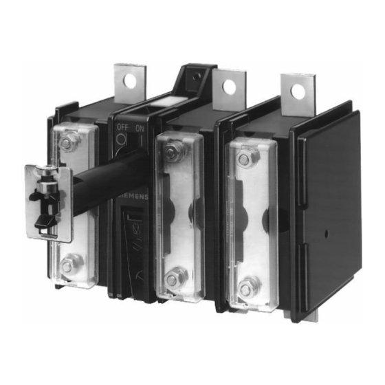
Siemens 3KA52 Folleto - Página 4
Navegue en línea o descargue pdf Folleto para Interruptor Siemens 3KA52. Siemens 3KA52 50 páginas. Switch-disconnector
También para Siemens 3KA52: Instrucciones de uso (5 páginas)

SENTRIC Switch Disconnectors
SENTRIC LD Main Control and EMERGENCY STOP Switches from 16 A to 125 A
General data
■
Technical specifications
Standards
Switch
Number of contacts
Rated insulation voltage U
Rated operating voltage U
Rated frequency
Rated impulse withstand voltage U
Rated short-time withstand current (1 s current, rms value)
Short-circuit protection, max. back-up fuse (gL)
Rated uninterrupted current I
AC-21A load-break switch
AC-3 motor load switch
in-service switching
of individual motors
AC-23A main control switch
Maintenance switch
frequent, but not
in-service switching
of individual motors
Power loss per conducting path at I
7
Touch protection to DIN VDE 0106 Part 100
Mechanical endurance
Operating frequency
Permissible ambient temperature
Isolating characteristics
Main control and EMERGENCY-STOP switch characteristics
Conductor cross-sections for main conductors
Connection type
solid or stranded
flexible with end sleeve (max.)
Auxiliary switches
Rated insulation voltage U
Rated operating voltage U
Rated uninterrupted current I
Rated operating current I
Short-circuit protection, auxiliary switch, max. back-up fuse (gL/gG) A
Conductor cross-section for auxiliary conductors
Connection type
solid or stranded
Finely stranded with end sleeve
Standards
Switch
Rated operating voltage U
Rated uninterrupted current I
Conventional thermal current I
Max. rating (AC-3)
AC motors 40 Hz ... 60 Hz
(HP = PS)
Conductor cross-sections
Tightening torque
1) With appropriate operating mechanisms according to DIN VDE 0113 (see
selection and ordering data).
7/4
Siemens LV 10 · 2004
i
e
imp
u
Rated operating current I
Rating
at 220 V ... 240 V
at 380 V ... 440 V
at 660 V/690 V
Rating
at 220 V ... 240 V
at 380 V ... 440 V
at 660 V/690 V
e
i
e
u
AC-15
at 120 V
e
at 220 V ... 240 V
at 380 V ... 415 V
at 500 V
e
u
Current rating
Pilot duty
th
3 ∼ 120 V
240 V
480 V
600 V
1 ∼ 120 V
240 V
copper cable
DIN VDE 0660, IEC 60947
Type
3LD2 0
3LD2 1
3/4
3/4
V
690
690
AC V
690
690
Hz
50 ... 60
50 ... 60
kV
6
6
A
340
640
A
20
25
A
16
25
A
16
25
e
kW
3.0
4.0
kW
5.5
7.5
kW
5.5
7.5
kW
4.0
5.0
kW
7.5
9.5
kW
7.5
9.5
W
0.5
1.1
yes
yes
Oper-
100 000
100 000
ating
cycles
1/h
50
50
°C
–25 ... +55
–25 ... +55
up to ...
690
690
V
1)
yes
yes
Clamp connections
2
mm
1 ... 6
1.5 ... 16
2
mm
4
10
V
500
500
AC V
500
500
A
10
10
A
6
6
A
3
3
A
1.8
1.8
A
1.4
1.4
10
10
Clamp connections
2
mm
2 ×
1 ×
(0.75 ... 2.5)
(0.75 ... 4)
2
mm
2 ×
1 ×
(0.75 ... 2.5)
(0.75 ... 2.5)
UL/CSA
Type
3LD2 0
3LD2 1
AC V
600
600
A
10
20
600 A
600 A
P600
P600
A
16
25
HP
1
–
HP
3
7.5
HP
7.5
10
HP
10
15
HP
0.5
2
HP
1.5
3
AWG
18 ... 10
14 ... 8
Nm
1.5 ... 2
2 ... 2.5
3LD2 2
3LD2 5
3LD2 7
3/4
3/4
3/4
690
690
690
690
690
690
50 ... 60
50 ... 60
50 ... 60
6
6
6
640
1260
2000
50
63
100
32
63
100
32
63
100
5.5
11.0
18.5
9.5
18.5
30.0
9.5
15.0
22.0
6.0
11.0
18.5
11.5
22.0
37.0
11.5
18.5
30.0
1.8
4.5
7.5
yes
yes
yes
100 000
100 000
100 000
50
50
50
–25 ... +55
–25 ... +55
–25 ... +55
690
690
690
yes
yes
yes
1.5 ... 16
2.5 ... 35
4 ... 50
10
16
35
500
500
500
500
500
500
10
10
10
6
6
6
3
3
3
1.8
1.8
1.8
1.4
1.4
1.4
10
10
10
1 ×
1 ×
1 ×
(0.75 ... 4)
(0.75 ... 4)
(0.75 ... 4)
1 ×
1 ×
1 ×
(0.75 ... 2.5)
(0.75 ... 2.5)
(0.75 ... 2.5)
3LD2 2
3LD2 5
3LD2 7
600
600
600
30
60
100
600 A
–
–
P600
32
63
100
–
–
–
10
15
30
20
40
60
30
50
75
2
–
–
3
10
–
14 ... 8
14 ... 6
12 ... 1
2 ... 2.5
2.5 ... 3
2.5 ... 3
3LD2 8
3/4
690
690
50 ... 60
6
2000
125
125
125
22.0
37.0
30.0
22.0
45.0
37.0
12
yes
100 000
50
–25 ... +55
690
yes
4 ... 50
35
500
500
10
6
3
1.8
1.4
10
1 ×
(0.75 ... 4)
1 ×
(0.75 ... 2.5)
3LD2 8
600
125
–
125
–
40
75
100
–
–
12 ... 1
2.5 ... 3
