INPUT CONNECTIONS
7
8
13 14
15
16 17
18
4
5
6
7
8
9 10 11
12
1
2
3
1
2
3
4
5
6
LEDS
STS – STATUS LED
The Status LED is a dual color LED that provides information regarding the
state of the module. This includes indication of the various stages of the start-up
routine (power-up), as well as any errors that may occur.
Startup Routine
Rapidly Flashing Red
Module is currently being flash upgraded. This occurs
for four seconds during a power up.
Steady Red
Module switching to configuration.
Green
Module performing normally.
FIRMWARE UPGRADE
The module's firmware is stored in flash memory so that software/hardware
conflicts are avoided, and so that software features may be added in the future.
During a download, RD500 software compares its own library of firmware files
with those stored in the RD500 module. If they do not match, RD500 software will
download the necessary files. The RD500 then checks to make sure that the I/O
modules contain the same firmware. If they contain a different revision, the
RD500 will automatically copy those files into the module's flash memory. During
this process, the module LEDs will flash rapidly, starting with the top row, and
progressing through the remaining rows until the process is complete.
7ML19985MB01
WARNING - EXPLOSION HAZARD - DO NOT DISCONNECT
WHILE CIRCUIT IS ALIVE UNLESS HAZARDOUS
CONDITIONS ARE NOT PRESENT.
INPUT AND OUTPUT (I/O) WIRING MUST BE IN
ACCORDANCE WITH CLASS I, DIV. 2 WIRING METHODS
AND IN ACCORDANCE WITH THE AUTHORITY HAVING
JURISDICTION.
Error States
Solid Red
Green/Pulsing Red
ALM – ALARM LED
The Alarm LED indicates the presence of an input fault condition. When one or
more Input Fault Alarm bits is high, the LED turns on. The alarms may be disabled
for unused inputs.
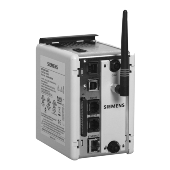
SITRANS RD500
Module not controlling, and not communicating.
Module is controlling properly, but has lost
communication with the RD500.
Page 4