Cisco 2811 Series Operaciones - Página 3
Navegue en línea o descargue pdf Operaciones para Enrutador de red Cisco 2811 Series. Cisco 2811 Series 31 páginas. 2800 series integrated services routers
También para Cisco 2811 Series: Ficha de datos (20 páginas), Instalación y actualización (14 páginas), Operaciones (31 páginas), Manual de inicio rápido (47 páginas)
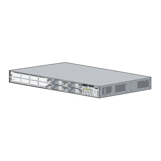
The Cisco 2811 Cryptographic Module Physical Characteristics
Figure 1
The Cisco 2811 router is a multiple-chip standalone cryptographic module. The router has a processing
speed of 350MHz. Depending on configuration, either the internal NetGX chip or the IOS software is
used for cryptographic operations.
The cryptographic boundary of the module is the device's case. All of the functionality discussed in this
document is provided by components within this cryptographic boundary.
The interface for the router is located on the rear and front panels as shown in
respectively.
Figure 2
Cisco 2811 Front Panel Physical Interfaces
7
SYS
AUX/
SYS
PWR
PWR
ACT
CF
COMPACT FLASH
Do Not Remove During Network Operation
Figure 3
Cisco 2811 Rear Panel Physical Interfaces
1
The Cisco 2811 router features a console port, an auxiliary port, two Universal Serial Bus (USB) ports,
four high-speed WAN interface card (HWIC) slots, two10/100 Gigabit Ethernet RJ45 ports, an Enhanced
Network Module (ENM) slot, and a Compact Flash (CF) drive. The Cisco 2811 router supports one
single-width network module, four single-width or two double-width HWICs, two internal advanced
integration modules (AIMs)
connections, and 16 ports of IP phone power output. The
OL-8663-01
The Cisco 2811 router case
SY S
AU X/
PW R
SY S
PW R
AC T
CF
CO NS OL
CO MP AC
1
E
T FLA SH
OP TIO NA
L RP S INP
UT
Do No t Re
mo ve Du
0
ring Ne two
AU X
rk Op era
tion
12V
11A
-48 V
4A
6
5
4
CONSOLE
1
AUX
0
8
1
, two internal packet voice data modules (PVDMs), two fast Ethernet
Cisco 2811 and Cisco 2821 Integrated Services Router FIPS 140-2 Non Proprietary Security Policy
100 -24 0
V~ 4A
50/ 60 Hz
3
OPTIONAL RPS INPUT
12V
11A
7
H
W
I
C
3
H
W
I
C
1
5
Figure 2
Cisco 2811 and Cisco 2821 Routers
Figure 2
and
2
1
100-240 V~ 2A
50/60 Hz
6
H
W
I
A= ACT
A= FDX
C
S= SPEED
A= LINK
2
A
FE 0/1
FE 0/0
F
H
S
W
I
L
C
0
PVDM1
PVDM0
AIM1
AIM0
4
3
2
shows the front panel and
Figure
3,
1
A
F
S
L
Figure 3
3