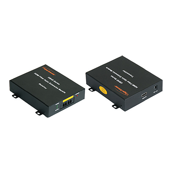
DigitaLinx DL-HDFO Manual del usuario - Página 8
Navegue en línea o descargue pdf Manual del usuario para Extensor DigitaLinx DL-HDFO. DigitaLinx DL-HDFO 13 páginas. Fiber optic extender

4.) Remove the dust covers from the Fiber Optic LC receptacles and connect each
Duplex LC cable one by one to each of the four LC receptacles. Plug A to A and
B to B. Carefully recheck polarities and ensure the duplex connectors are fully
engaged and locked in place.
4.) Remove the dust covers from the Fiber Optic LC receptacles and connect each Duplex LC cable
5.) Connect the RJ45 plug to each RJ45C receptacle of the TX
one by one to each of the four LC receptacles. Plug A to A and B to B. Carefully recheck
and RX boxes.
polarities and ensure the duplex connectors are fully engaged and locked in place.
5.) Connect the RJ45 plug to each RJ45C receptacle of the TX and RX boxes.
6.) Connect the DC power supply to either the TX or the RX unit depending on
6.) Connect the DC power supply to either the TX or the RX unit depending on your availability of
and AC power source. This will power up both of the units. The power receptacle is located on
your availability of and AC power source. This will power up both of the units.
the same side as the HDMI receptacle. Ensure both units have power by viewing the power LED.
The power receptacle is located on the same side as the HDMI receptacle.
SAFETY NOTE: Do NOT unplug the LC connectors and look directly into the connector or
Ensure both units have power by viewing the power LED. SAFETY NOTE:
receptacle when operating. This device is regulated as Laser Class 1 and severe eye damage can
result.
Do NOT unplug the LC connectors and look directly into the connector or
7.) Power up the Display side (Display can reference Media Receiver, Computer Monitor or Display).
receptacle when operating. This device is regulated as Laser Class 1 and severe
8.) Power up the Source side.
9.) The Status LED on both the TX and RX units should be illuminated Green. If it is not illuminated
eye damage can result.
check the Polarity on the LC connectors. Failure of the LED to illuminate can be caused by a poor
7.) Power up the Display side (Display can reference Media Receiver, Computer
fiber connection, broken fiber, or incorrect polarity on the LC plugs.
Monitor or Display).
a.) Tip – After initial power up shut down all displays and sources and repeat the start up
operation
8.) Power up the Source side.
b.) Do not "Hot Plug" the TX and RX units. Ensure sources and displays are powered down
9.) The Status LED on both the TX and RX units should be illuminated Green. If it
prior to hookup.
10.) Note: It is recommended to use the longest run of cable between the source and the Fiber Optic
is not illuminated check the Polarity on the LC connectors. Failure of the LED to
Extender followed by a shorter run when possible to reap the greatest benefit of the signal boost.
illuminate can be caused by a poor fiber connection, broken fiber, or incorrect
11.) The length of the HDMI or DVI cable on the source side should be 8 meters or less due to source
polarity on the LC plugs.
signal inconsistencies. The length from the RX unit to the display should be one size less then the
source side. For example an 8 meter cable on the source would have a 7 meter or shorter cable on
a.) Tip – After initial power up shut down all displays and sources and repeat the
the display side.
start up operation
b.) Do not "Hot Plug" the TX and RX units. Ensure sources and displays are
powered down prior to hookup.
10.) Note: It is recommended to use the longest run of cable between the source
and the Fiber Optic Extender followed by a shorter run when possible to reap
the greatest benefit of the signal boost.
11.) The length of the HDMI or DVI cable on the source side should be 8 meters
or less due to source signal inconsistencies. The length from the RX unit to the
display should be one size less then the source side. For example an 8 meter
cable on the source would have a 7 meter or shorter cable on the display side.
Installation Continued
Installation Procedures Continued
DL-HDFO TX Unit
1
2
3
4
DL-HDFO RX Unit
2
1
4
3
Page 1-7
Features
1-7
