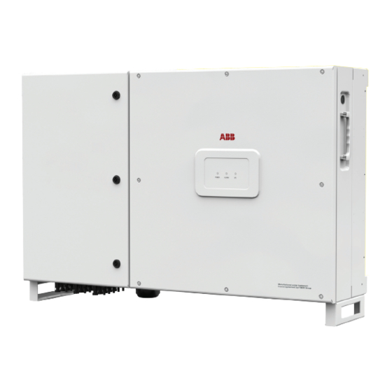
Fimer PVS-60-TL Manual de instalación rápida - Página 4
Navegue en línea o descargue pdf Manual de instalación rápida para Equipamiento industrial Fimer PVS-60-TL. Fimer PVS-60-TL 8 páginas. Solar inverter

4. Lifting and transporting
Transport and Handling
Transport of the equipment especially by road, must be carried out
with means for protecting the components ( in particular, the electronic
components) from violent shock humidity vibration etc. During handling,
do not make any sudden or fast movements that can create dangerous
swinging.
Lifting
FIMER usually stores and protects individual components by suitable
means to make their transport and subsequent handling easier, but as a
rule, it is necessary to utilize the experience of specialized staff in change
of loading and unloading the components. Do not lift several units or parts
of the equipment at the same time unless otherwise indicated.The ropes
and equiment used for lifting must be suitable for bearing the weight of
the equipment.
Unpacking and Checking
The packaging components must be removed and disposed of according to all
applicable laws and regulations of the country where the equipment is
being installed. When you open the package, check that the equipment
is not damaged and make sure all components are present. If you notice
any defects or damage, stop unpacking and contact the carrier, and also
promptly inform the FIMER Service department.
Model
Weight (kg)
PVS-50-TL / PVS-60-TL
70 kg/159lbs
5. Supplied Component list
Components supplied with the inverter
Mounting bracket (1) + screws for
bracket mounting
Locking brackets (2) + screws for the
locking bracket mounting
Wireless antenna
Configurable relay connectors
Control and communications signal
connectors
Two-hole gasket for PG 21 signal
cable glands (13) + cap
M6 screw for securing the:
Protective earth terminal (internal) (37)
Protective earth terminal (external) (16)
M6 toothed washer for securing the:
2x Protective earth terminal (internal) (37)
2x Protective earth terminal (external) (16)
Configuration bar for paralleled input
channels and M5x12 screws (with
plain and split washers)
Key for front door key-lock (8)
Technical documentation
6. Mounting instructions
The mounting bracket (1) can be used to install the inverter on a vertical
or horizontal support
1. Position the bracket (1) perfectly level on the support and use it as a
drilling template. (FIG. 1)
2. It is the installer's responsibility to choose an appropriate number and
distribution of attachment points. The choice must be based on the
type of support (wall, frame or other support), the type of anchors to
be used and their ability to support 4 times the inverter's weight (4
x 70 kg=280 kg for all models). Attach the bracket to the wall with at
least 10 attachment screws. Depending on the type of anchor chosen,
drill the required 10 holes (A) to mount the bracket. Put at least four
screws in the upper side and at least four in the lower side (see
example in the illustration).
3. Fix the bracket to the support. (FIG. 2)
4. Lift the inverter using the handles (14), or another appropriate lifting
device. The inverter is pre-equipped with lower support (24) which
allow it to be temporarily put vertically on the floor to make it easier the
lifting. (FIG. 3 and 4).
5. Insert the heads of six anchor point (3), present on the bracket into the
slots
on the rear of the inverter. (FIG. 5)
6. Install the 4 fixing braket (2) on the 4 corner of the inverter (using 8
screws). (FIG. 6)
7. Remove the protective cover from the connector of the wireless antenna
located on the left side of the inverter. Install the wireless antenna by
screwing it into the specific connector (10). (FIG. 7)
8. Open the wiring box front door (4) turning the 3 key-lock (8) in "OPEN"
position and proceed with the wiring and connections depending on
the model. (FIG. 8)
A
A
A
1
A
A
A
A
A
01
Q.ty
1+6
03
4+8
1
3
2
05
2
2+2
2
07
4
1+3
1
A
A
A
A
1
A
A
A
A
A
A
A
A
02
A
A
04
06
08
A
A
A
A
A
A
A
A
2
OPEN
OPEN
3
LOCK
LOCK
4
