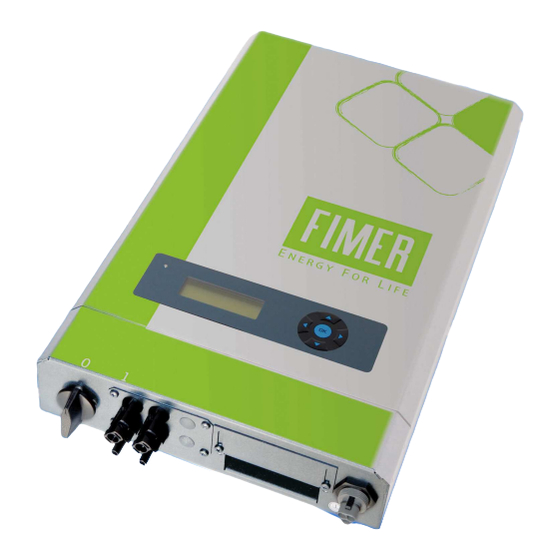
Fimer R55 Series Manual - Página 8
Navegue en línea o descargue pdf Manual para Módem Fimer R55 Series. Fimer R55 Series 12 páginas. Grid connected pv inverter internal and external gsm modem user guide for single-phase inverter
También para Fimer R55 Series: Manual del usuario (16 páginas)

________________________________________________________________________________
Enter the temperature coefficient of the output of the PV generator here. You can find the values in
the data sheet of the modules.
Note that the temperature coefficient is negative, but that you have to enter a positive figure here.
Example: The modules used have a temperature coefficient of γ (P_MPP) = -0.33%/°C. In this case
enter the value 0.33%/°C.
Parameter number 280: Yield variation alarm threshold
Menu
Short Description
Unit
Accuracy
Under this parameter, you enter the value for variation between the yield of the inverter and the
"theoretical yield" of the sensor or between the yields of all the inverters in the installation,
referenced to the nominal DC output. If this value is overshot, an alarm is activated.
Parameter number 283: Activation code for yield monitoring
Menu
Short Description
Default value
Enter the code given to you by FIMER.
7.4 Data evaluation
Parameter number 220: Sensor output
Menu
Short Description
Unit
The instantaneous output of the PV generator to be expected in theory is calculated here on
the basis of the irradiation sensor reading, the total module surface area, the module
efficiency, the module temperature and the output temperature coefficient of the modules.
Note that this theoretical output always deviates greatly compared with the actual output of the PV
generator. This is due to the different materials used in the cells of the generator and sensor,
different temperatures, and possible shadowing or soiling. Parameter 220 serves as a rough guide
or interim value for display under parameters 216 and 219.
Parameter number 216: Yield of the sensor today
Menu
Short Description
Unit
The day yield meter of the sensor displays the "day yield" calculated for the sensor. It is used to
compare the actual day yield (see parameter 8) with the theoretical, calculated "yield" of the sensor.
Based on the module surface area, module efficiency and module temperature coefficient, we
recommend that after a certain length of time (e.g. 1 to 2 months) you set the "day yield of the
sensor" manually such that the sensor yield value is roughly equal to the actual yield. This will
enable you to detect module or string failures (or failure of the sensor) if they arise.
_____________________________________________________________________________
6
Installation Monitoring
EAW
kWh/kW
0,500 kWh/kW
Installation Monitoring
FSC
0
Environment
PSENS
W
Environment
SET
Wh
