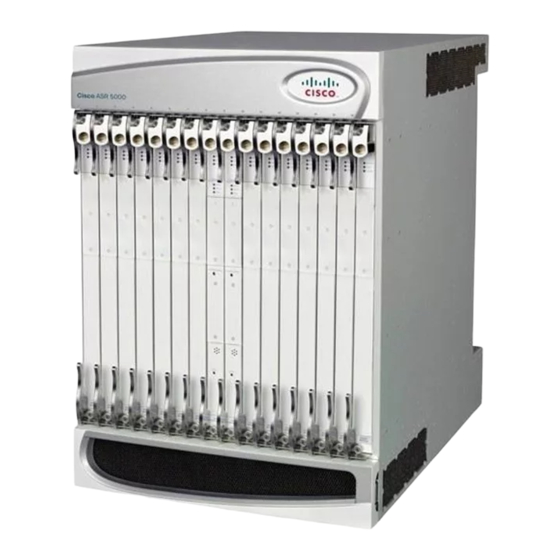
Cisco ASR 5000 Procedimiento de instalación - Página 5
Navegue en línea o descargue pdf Procedimiento de instalación para Pasarela Cisco ASR 5000. Cisco ASR 5000 8 páginas. Applying power and verifying the installation
También para Cisco ASR 5000: Manual de instalación (18 páginas), Manual de instalación (33 páginas), Manual de instalación (37 páginas)

Installation Procedure Overview
• Pallet jack and/or chassis lift to move and position the ASR 5000 chassis. Without such mechanical
Site Prerequisites
This section summarizes power, grounding, environment, and clearance requirements that must be met prior
to installing and operating the ASR 5000. For detailed information, refer to the Technical Specifications
chapter.
Power and Grounding
Each PFU requires a power feed of 160A @ -48VDC (nominal). The feeds should be routed to the installation
rack from the site power supply using adequately sized conductors and circuit breakers in accordance with
local electrical codes.
The chassis must be grounded to a site ground point using the recommended conductors and lugs. The ground
point should be in close proximity to the ASR 5000 chassis to assure adequate conductivity.
Environment
The site's heating ventilation and air conditioning (HVAC) systems must be sized to maintain the operating
temperatures and relative humidity specified in the Technical Specifications chapter. HVAC capacity
requirements will vary based on the system configuration and associated power draw, as well as the operational
characteristics of other equipment installed at the site.
Clearance
Adequate clearance must be maintained at the front and rear of the ASR 5000 chassis to assure proper air
flow and allow maintenance access for the installation, removal and replacement of components. The
recommended clearance is 30 to 36 inches (76 to 92 centimeters) at the front and rear of the chassis.
Protecting Against Electro-static Discharge
Electro-Static Discharge (ESD) can cause serious damage to sensitive components on the chassis, its
sub-components, and/or the cards installed in the chassis. To prevent damage from ESD, you must take proper
grounding precautions before handling the chassis or any of its components.
To aid in the prevention of ESD damage, the chassis and its mounting brackets are equipped with ESD jacks.
Use the jacks in conjunction with grounding wrist straps when handling the chassis and/or its components.
The following figure shows the location of the jacks.
assistance, moving and positioning the chassis will require multiple craftpersons trained to safely handle
heavy rack-mounted units.
Site Prerequisites
ASR 5000 Installation Guide
5
