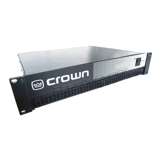
Crown 1400 CSL Manual de referencia - Página 10
Navegue en línea o descargue pdf Manual de referencia para Amplificador Crown 1400 CSL. Crown 1400 CSL 19 páginas. Crown 1400csl: specifications
También para Crown 1400 CSL: Dibujos (2 páginas)
This protection circuitry is activated in unusual situa-
tions where the unit's transformer temperature rises to
unsafe levels. Under these abnormal conditions, the
unit removes power to the high voltage transformer (the
fan will also run in 120 VAC, 60 Hz units). The amplifier
will return to normal after it cools to a safe temperature.
It is very unlikely that you will ever see a CSL amplifier
activate transformer thermal protection as long as it is
operated within rated conditions. The amplifier is de-
signed to keep working under conditions where other
amplifiers would fail. But even when the limits of a CSL
are exceeded, it still protects itself—and your invest-
ment—from damage.
3.3.5 Fuses and Circuit Breakers
The power supplies for the 460 CSL and 800 CSL are
protected by fuses, while the power supplies for the
1400 CSL are protected by a circuit breaker. With rated
loads and output levels, these fuses (or the circuit
breaker) should only shut down the amplifier in the in-
credibly rare instance of a catastrophic amplifier fail-
ure. Other protection systems such as ODEP keep the
amplifier operational under most other severe condi-
tions. The fuses (or breaker) can also shut down the
amplifier in situations where extremely low-impedance
loads and high output levels result in current draw that
exceeds their rating. Again, this should only be pos-
sible when operating outside rated conditions , such as
driving a 1 ohm load or overloading the input and cre-
ating a severely clipped signal.
All 120 VAC, 60 Hz units and all 1400 CSL units have a
separate fuse for the low-voltage power supply and
cooling fan. Additionally, all units have separate fuses
(or a breaker) for the high-voltage power supplies.
A CSL amplifier will not blow its fuses (or breaker) un-
less something is wrong. In the rare event that an inter-
nal fuse blows, please refer the unit to a qualified
technician. If the breaker in a 1400 CSL trips, try to iden-
tify and correct the problem before resetting the breaker
with the back panel reset switch. If the problem per-
sists, refer the unit to a qualified technician.
Page 10
3.4 Controls
The enable switch is located on the front panel so you
can easily turn the amplifier on and off. When making
any setup or wiring changes, don't forget to turn off the
amplifier, turn down the level controls and disconnect
the power cord. The back panel stereo/mono switch
is used to select Stereo, Bridge-Mono or Parallel-Mono
operating modes (see Sections 2.1 and 2.2). The level
controls are also located on the back panel. Be sure to
leave channel 2 turned down when using Bridge-Mono
mode. The back panel ground lift switch isolates the
phone jack input grounds from the chassis ground to
help prevent ground loops. It does not affect any in-
stalled input accessories. The input sensitivity switch
is located inside the back cover plate. It is used to set
the amplifier's input sensitivity (see Section 2.3). And
the 1400 CSL has a back panel reset switch that is
used to reset the breaker that protects the amplifier's
power supplies (see Section 3.3.5).
CHANNEL 2
LEVEL CONTROL
CH-2
6
5
7
4
8
3
9
2
10
INPUT GROUND LIFT
1
11
0
12
LIFT
INPUT
GAIN
(AFFECTS PHONE INPUTS ONLY.)
Fig. 3.1 Back Panel Level Controls
3.5 Filter Cleaning
A dust filter is provided on the unit's air intake. If it be-
comes clogged, the unit will cool less efficiently and
may produce lower output levels. To clean, remove the
three phillips screws that secure the front grille. Use
mild dishwashing detergent and warm water for best
results. New filters may be ordered from the factory.
Dust filters are not 100% efficient—depending on the
local environment, the internal heat sinks of the ampli-
fier will benefit from periodic cleaning by a qualified
technician. Internal cleaning information is available
from our Technical Support Group.
CSL Series Power Amplifiers
CHANNEL 1
LEVEL CONTROL
CH-1
6
5
7
4
8
3
9
2
10
1
11
0
12
INPUT
GAIN
(MONO)