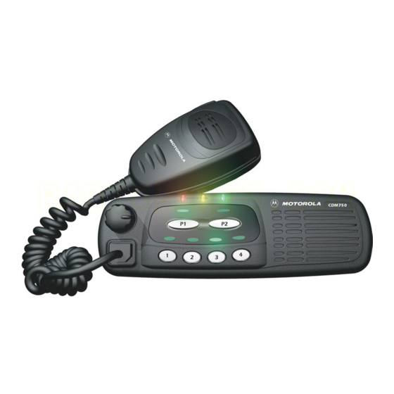
Motorola CDM750 Manual de servicio e instalación - Página 17
Navegue en línea o descargue pdf Manual de servicio e instalación para Radio bidireccional Motorola CDM750. Motorola CDM750 32 páginas. Professional series
mobile radio
También para Motorola CDM750: Manual del usuario (28 páginas)

Overview
This section contains information about the setup and instal-
lation of the CDM Control Station.
General considerations
The Control Station is a very flexible unit with various set-
tings to accommodate most installation configurations. Care
must be taken in configuring the Control Station prior to
final installation.
Interface Module settings
The Control Station Interface Module (CSIM) contains sev-
eral programmable operational features via switch settings
and jumpers. Various audio level settings are also accom-
plished with adjustment pots and jumper settings.
Switch Settings
SW1 located on the back panel of the inner chassis allows
one to specify microphone input and various audio routings.
Switch 1, Intercom/Parallel TX Audio Enable
When switch 1 is on, accessory mic (parallel) audio is routed
to the speaker, enabling Intercom and monitoring of acces-
sory transmissions by the base user.
Switch 2, Intercom Audio From the Control Station
to Accessory TX Port
When switch 2 is on, base station mic audio (from any source
– headset, local mic, or desk mic) is routed to the accessory
TX audio port. This feature is to enable Intercom and moni-
toring of base station transmissions by desk sets that are
equipped with the ability to monitor TX audio.
Switch 3, Intercom Audio From the Control Station
to Accessory RX Port
When switch 3 is on, base station mic audio (from any source
– headset, local mic, or desk mic) is routed to the accessory
RX audio port. This feature is to enable Intercom for desk
sets that are not equipped with the ability to monitor TX
audio.
October, 2004
CDM Control Station Installation
Switch 4, Mute Accessory RX Audio During
Intercom
When switch 4 is on, radio RX audio to the accessory RX
Audio line will be muted during Intercom (pushing the front
panel "Intercom" button).
Switch 5, Intercom Audio From Local Mic
When switch 5 is on, the selected mic source for base station
Intercom (pushing the front panel "Intercom" button) is the
internal microphone.
Switch 6, Intercom Audio From Desk Mic
When switch 6 is on, the selected mic source for base station
Intercom (pushing the front panel "Intercom" button) is the
desk microphone.
Switch 7, Intercom Audio From Headset Mic
When switch 7 is on, the selected mic source for base station
Intercom (pushing the front panel "Intercom" button) is the
headset (if a headset is detected). If a headset is not detected
(plugged in), Intercom audio will come from the front panel
microphone.
Switch 8, Accessory Transmit Mutes Local Speaker
When switch 8 is on, the local speaker will be disabled when
an accessory device keys the radio transmitter. This is desir-
able to prevent feedback when the accessory device is located
in close proximity with the base station.
Default Settings
The Control Station ships from the factory with all switch
settings in the ON position.
Jumper Settings
Additional configuration options are available on the Con-
trol Station Interface Module (CSIM) board. The board must
be removed from the inner chassis to change the default
jumper settings. Refer to Table 3-1 for a description of the
available settings.
Adjusting Audio Levels
Although nominal audio levels have been preset at the fac-
tory, these levels should be adjusted to meet the unique
6880309N15-A
Section 3
3-1
