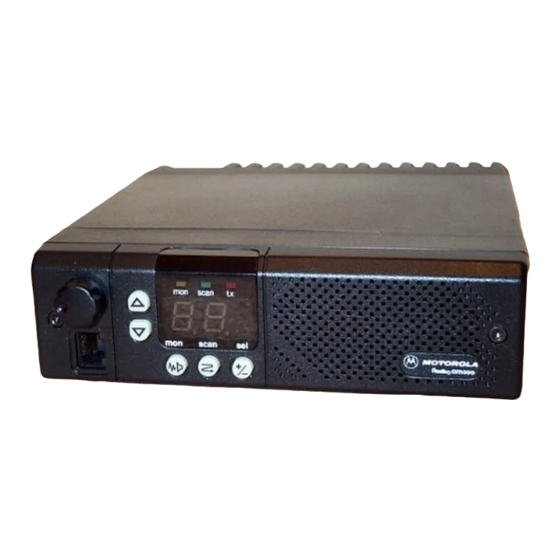
Motorola RADIUS GM300 Manual de servicio - Página 42
Navegue en línea o descargue pdf Manual de servicio para Radio Motorola RADIUS GM300. Motorola RADIUS GM300 49 páginas. 16-channel, conventional fm radio
También para Motorola RADIUS GM300: Manual de servicio (28 páginas), Manual de instrucciones (18 páginas), Manual de instrucciones (19 páginas), Manual del usuario (37 páginas), Instrucciones de uso (2 páginas)

Overview
This section explains the operation of the reference oscillator and lists all non-Þeld serviceable components in the
GM300 moible radios.
Operation of the Reference Oscillator
The frequency stability of the reference oscillator in the GM300 mobile radios is maintained by electronically mea-
suring the temperature of the oscillatorÕs crystal, computing the control voltage needed to accurately compensate
for the temperature-dependent frequency shift of the crystal, and applying this voltage to the tuning varactors in
the oscillator circuit.
For accurate temperature compensation, the characteristics of the oscillator and crystal are measured at the factory,
and this information is programmed into the microcomputer on the logic board.
Non-Field Servicable Components
Field-replacement of the microcomputer on the logic board, or of any components in the reference oscillator or tem-
perature-sensing circuit on the RF board, will impair the accuracy of this compensation technique. For this reason,
these components cannot be replaced in the Þeld . If any of these components require service, the entire RF or logic
board must be replaced. The Radio Service Software calibration procedure for board replacement must be per-
formed after the new board has been installed. This step re-enters the temperature characteristic of the new oscilla-
tor into the old microcomputer, or vice-versa.
The following components are not Þeld-serviceable:
Ref. No.
_________________________________________________________________________________________________
C151
C152
C153
C154
C155, 156
C157
C158
C159
C160
C161
C163
C164
C165
C166 thru 168
C176
C177
CR151, 152
CR153
L151
L152
Q151
Q152
R151
R152
R153
R154
R155
R156
R157
R158
R161
March, 1997
Non-Field Servicable Components
Part No.
Description
21-13740B73
chip capacitor, 1000 pF
21-13740B47
chip capacitor, 82 pF
21-13740B25
chip capacitor, 10 pF
21-13741B45
chip capacitor, .01 uF
21-13740B55
chip capacitor, 180 pF
21-13741B45
chip capacitor, .01 uF
08-11051A15
poly capacitor, 0.22 uF, 63 V
21-13740B35
chip capacitor, 27 pF
21-13740B29
chip capacitor, 15 pF
21-13740B73
chip capacitor, 1000 pF
08-11051A17
poly capacitor, 0.47 uF, 63 V
21-13741B69
chip capacitor, 0.1 uF
21-13740B73
chip capacitor, 1000 pF
21-13740B49
chip capacitor, 100 pF
21-13740B73
chip capacitor, 1000 pF
21-13741B69
chip capacitor, 0.1 uF
48-80006E10
silicon varactor SOT
48-84336R03
dual silicon SOT MMBD7000
24-80299D01
coil, tunable 17-3/4 turns
24-11087A35
chip coil, 5.6 uH, 10%
48-11043C19
NPN; type M43C19/M9658
48-11043C06
PNP; type M43C06/M9643
06-11077B15
chip resistor, 47k
06-11077B11
chip resistor, 33k
06-11077B15
chip resistor, 47k
06-11077A34
chip resistor, 22
06-11077A98
chip resistor, 10k
06-11077B03
chip resistor, 15k
06-11077A78
chip resistor, 1.5k
06-11077A74
chip resistor, 1k
06-11077A98
chip resistor, 10k
68 No.
Section 4
Location
RF Board
RF Board
RF Board
RF Board
RF Board
RF Board
RF Board
RF Board
RF Board
RF Board
RF Board
RF Board
RF Board
RF Board
RF Board
RF Board
RF Board
RF Board
RF Board
RF Board
RF Board
RF Board
RF Board
RF Board
RF Board
RF Board
RF Board
RF Board
RF Board
RF Board
RF Board
4-1
