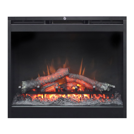
Dimplex BF9000 Manual de servicio - Página 13
Navegue en línea o descargue pdf Manual de servicio para Chimenea de interior Dimplex BF9000. Dimplex BF9000 18 páginas. Dimplex
También para Dimplex BF9000: Manual de servicio (17 páginas), Manual del usuario (19 páginas), Manual del usuario (20 páginas), Manual de solución de problemas (2 páginas), Manual del usuario (19 páginas)

- 1. Exploded Parts Diagram: Df2426, Df2550, Dfg2562, 6905050100-500
- 2. Wiring Diagram: Df2426, Df2550, Dfg2562, 6905050100-500
- 3. Exploded Parts Diagram - Bf9000, 6907560100
- 4. Wiring Diagram - Bf9000, 6907560100
- 5. Light Assembly Replacement
- 6. Flicker Motor/Flicker Rod Replacement
- 7. Heater Assembly Replacement
- 8. Troubleshooting Guide
them onto the same location on the new receiver
board.
!
NOTE: Using a flat head screwdriver gently pry
between the end of the connector and the circuit board to
release the wires.
6. Remove the old board off the plastic mounts, by
squeezing the tab inward and sliding the board off.
7. Replace any plastic mounts that may have broken by
pushing the old mounts out towards the back. Replace
the new mounts from the back.
8. Line up the holes on the corners of the new remote
control receiver board and press the new board onto
the mounts. Make sure the board is secure.
9. Re-assemble in reverse order as described above.
LED LOG DRIVER REPLACEMENT
Tools Required: Philips head screwdriver
Needle nose pliers
Small cutter or snips
CAUTION: Follow "Preparation for Service" instructions
before proceeding.
1. Remove 9 screws that secure the top panel to the side
panels of the firebox using a Philips head screwdriver,
2 on the left side; 2 on the right side; 3 on the backside;
2 on the top.
2. Lift the top panel up off the firebox, turn it 45 degrees
and rest it inside the upper cavity against the back
panel.
CAUTION: Support the back underside of the firebox
with a small piece of wood as the feet do not go the entire
depth of the unit and it can easily tip backwards.
3. Taking note of the original location of each wire con-
nected to the board, remove each wire and connect
then onto the same location on the new log driver
board.
!
NOTE: Using a flat head screwdriver gently pry
between the end of the connector and the circuit board to
release the wires.
4. Remove the old board off the plastic mounts, by
squeezing the tab inward and sliding the board off.
5. Replace any plastic mounts that may have broken by
pushing the old mounts out towards the top. Replace
the new mounts from the back.
6. Line up the holes on the corners of the new log driver
board and press the new board onto the mounts. Make
sure the board is secure.
7. Re-assemble in reverse order as described above.
POWER CORD REPLACEMENT
Tools required: Phillips head screw driver.
Needle nosed pliers.
CAUTION: Follow "Preparation for Service" instructions
before proceeding. Steps 1 & 2 only.
1. Remove power cord junction box cover by removing
the 2 Philips screws mounted to the back panel of the
fireplace.
2. Unscrew the 2 wire connectors that join the power cord
at the bottom to the wire leads coming down from the
top.
3. With a pair of needle nose pliers, open the strain relief
bushing that holds the power cord in place on the junc-
tion box cover and remove the cord.
4. Feed the new power cord through the junction box and
squeeze the new strain relief in place on the cord and
junction box.
5. Re-connect wires. –(Wide blade on the plug is the neu-
tral side of the power cord).
6. Re-assemble in the reverse order as above.
13
